4 non-safety input devices – Banner SC22-3E Safety Controller with Ethernet User Manual
Page 31
CAUTION: . . . Debounce and Response
Any changes in the closed-to-open debounce time will affect the Safety Output response (turn OFF) time. This value
is computed and displayed for each Safety Output when a configuration is created. The values are also listed in the OBI and
the PCI Configuration Summary documents. (Default setting is 6 ms.)
Open-to-Closed Debounce Time (from 10 to 500 milliseconds in 1 ms intervals, except 10 to 1,500 ms for mute sensors). The
open-to-closed debounce time is the time limit required for the input signal to transition from the low (0V dc) state to the steady high (24V
dc) state. This time limit may need to be increased in cases where high magnitude device vibration, impact shock, or switch noise condi-
tions result in longer signal transition times. If the debounce time is set too short under these harsh conditions, the system may detect a
signal disparity fault and lock out. (Default setting is 50 ms.)
When a safety mat is used, the response time calculation for the safety mat is dependent on the Stop (6 to 100 ms) debounce time.
CAUTION: . . . Response Times
• The response time for a complementary device is based on the closed contact(s) opening,
not on the open con-
tact(s) closing. Both will lead to a stop signal, but only one determines the response time.
• Any changes in the open-to-closed debounce time will affect the Safety Output reaction (turn ON) time!
• The configurable debounce of an ON/OFF input and an enabling device input are not part of the calculated and confirmed
response times.
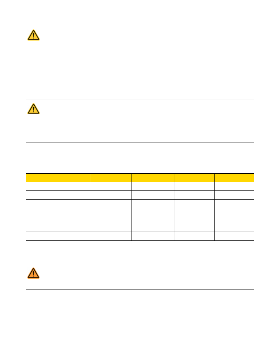
4.4 Non-Safety Input Devices
The non-safety input devices include manual reset devices, ON/OFF switches, and mute enable devices.
Configurable Properties
Manual Reset
ON/OFF
Mute Enable
Cancel OFF-Delay
Circuit Types
3
3
3
3
Input and Output Mapping
I/O
I/O
I/I
I/O
Debounce Times
Fixed at 50 ms
Closed-to-open:
6-100 ms
Open-to-closed:
10-500 ms
Fixed at 50 ms
Fixed at 50 ms
Monitored / Non-monitored
Yes
—
—
Yes
Manual Reset Devices. The manual reset is used to create a reset signal after a safety input device that has been configured to require
a manual reset has been opened and closed. After the manual reset operation is performed, any of the Safety Outputs controlled by that
safety input device can turn ON.
WARNING: . . . Non-Monitored Resets
If a non-monitored reset (either latch or system reset) is configured and if all other conditions for a reset are in place, a
short from the Reset terminal to +24V will turn ON the Safety Output(s) immediately.
ON/OFF Switch. The ON/OFF switch is used to provide a machine ON or OFF command. When all of the controlling safety inputs are in
the Run state, this function permits the Safety Output to turn ON and OFF. This is a single-channel signal; the Run state is 24V dc and
the Stop state is 0V dc. An ON/OFF input can be added without mapping to a Safety Output, which allows this input to control only a
Status Output.
Mute Enable Switch. The mute enable switch is used to signal the Controller when the mute sensors are permitted to perform a mute
function. When the mute enable function is configured, the mute sensors will not be enabled to perform a mute function until the mute
enable signal is in the Run state. This is a single-channel signal; the enable (Run) state is 24V dc and the disable (Stop) state is 0V dc.
SC22-3/-3E Safety Controller Instruction Manual
P/N 133487 rev. C
www.bannerengineering.com - tel: 763-544-3164
31