Rockwell Automation 2094-EN02D-M01-S1 Kinetix 6200 and Kinetix 6500 Safe Speed Monitoring Safety Reference Manual User Manual
Page 92
92
Rockwell Automation Publication 2094-RM001C-EN-P - May 2013
Chapter 8
Slave Modes for Multi-axis Cascaded Systems
Safe Stop
Change Safe Stop
Configuration
Stop Category
Safe operating stop type selection. This defines the type
of Safe Stop that is performed if the Safe Stop function
is initiated by a stop type condition.
Default:
Safe Torque-Off
Options:
Safe Torque-Off
Safe Stop 1
Safe Stop 2
Enable Standstill Checking
Automatically enabled for Safe Stop 1 and Safe Stop 2.
Default:
Standstill Checking Enabled
Options:
Standstill Checking Enabled
Standstill Checking Not Enabled
Safe Stop Monitor
Delay
Defines the monitoring delay between the request and
the Maximum Stop Time when the request for a Safe
Stop 1 or a Safe Stop 2 is initiated by an SS_In input ON
to OFF transition.
If the Stop Category is Safe Torque-Off with or without
Standstill Speed Checking, the Safe Stop Monitor Delay
must be 0 or an Invalid Configuration fault occurs.
Default:
0
Range:
0…6553.5 s
Deceleration
Reference Speed
Determines deceleration rate to monitor for Safe Stop 1
or Safe Stop 2.
Default:
0
Range:
0…65,535 rpm or mm/s
ratio based on revolutions or millimeters configuration
defined by the [Primary Feedback Units] parameter
Maximum Stop Time
Defines the maximum stop delay time that is used when
the Safe Stop function is initiated by a stop type
condition.
Default:
0
Range:
0…6553.5 s
Deceleration
Tolerance
This is the acceptable tolerance above the deceleration
rate set by the [Deceleration Reference Speed]
parameter.
Default:
0
Range:
0…100% of Deceleration Reference Speed
Standstill Speed
Defines the speed limit that is used to declare motion as
stopped.
Not valid for Safe Torque-Off without Standstill
Checking.
Default:
0.001
Range:
0.001…65.535 rpm or mm/s
ratio based on revolutions or millimeters configuration
defined by the [Primary Feedback Units] parameter
Standstill Position
Window
Defines the position limit window in encoder 1 degrees
or mm that is tolerated after a safe stop condition has
been detected.
Not valid for Safe Torque-Off without Standstill
Checking.
Default:
10
Range:
0…65,535 degrees (360° = 1 revolution) or mm
ratio based on revolutions or millimeters configuration
defined by the [Primary Feedback Units] parameter
Safety
Change System
Configuration
Door Control Output
Defines the lock and unlock state for door control output
(DC_Out).
Any Door Control Output option can be used for a
single-axis system or for the last unit in a multi-axis
system. The first and middle units of a multi-axis system
must be configured as 2 Channel Sourcing.
Default:
Power to Release
Options:
Power to Release
Power to Lock
2 Channel Sourcing
Input
Change Input
Configuration Type
Door Monitor
Configuration for the Door Monitor input (DM_In).
Option:
Solid State Device Equivalent 3 s
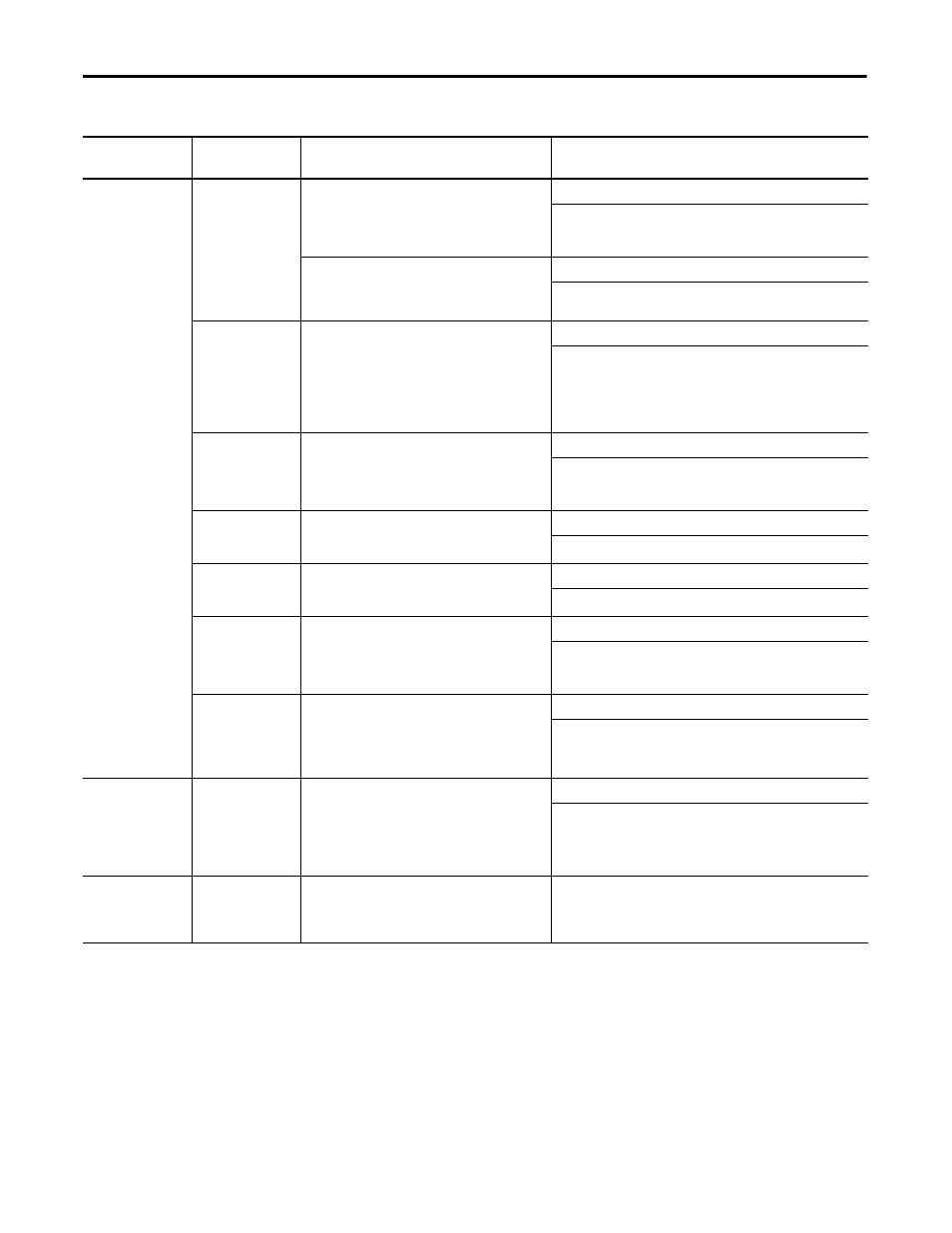
Table 27 - Slave, Safe Stop Parameters (continued)
Tab
Parameter Name
Description
Values
(Safety Configuration Tool)