Multi-axis connections, Multi-axis, Connections – Rockwell Automation 2094-EN02D-M01-S1 Kinetix 6200 and Kinetix 6500 Safe Speed Monitoring Safety Reference Manual User Manual
Page 101
Rockwell Automation Publication 2094-RM001C-EN-P - May 2013
101
Slave Modes for Multi-axis Cascaded Systems
Chapter 8
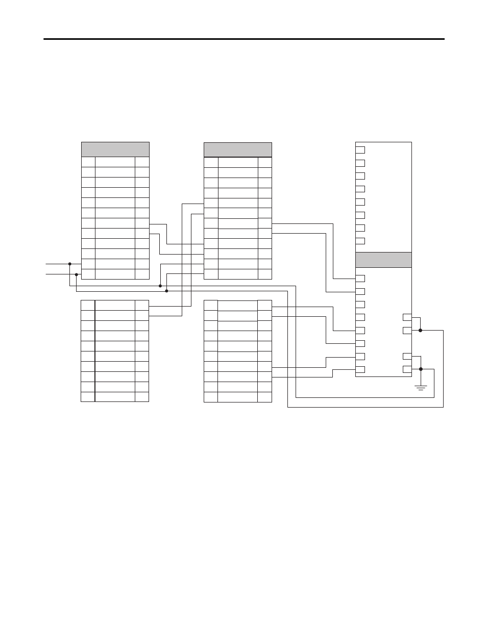
This second example is configured as a cascaded last unit via the [System
Configuration] parameter. It has SS_In, SLS_In, and DM_In input connections
from the previous upstream drive, but its SS_Out, SLS_Out, and DC_out
outputs are connected to a Bulletin 1791DS module.
Figure 35 - Slave, Safe Limited Speed Status Only, Last Drive
Multi-axis Connections
When configuring a multi-axis system, you need to consider the location of each
drive in the system. The type of cascaded connections that can be made are
dependent upon the Operation mode configurations of the master and slave
drives and their positions in the system.
Middle and last units in the cascaded chain can be configured for Automatic
reset. A single reset by the first unit also resets all following units in the chain. If a
fault occurs after the first axis in the cascaded chain, only the subsequent axis
enters the safe state. To reset all axes, you must cycle the SS_In input on the first
axis.
For slave units in a multi-axis system, the SS_In, SLS_In, and DM_In input
signal types (if used) must be configured for output switching signal devices
(OSSD) because the output from the previous unit is also configured for OSSD.
+24V DC
GND
In 7
In 6
In 5
In 4
In 3
In 2
In 1
In 0
V0
V1
G0
G1
Out 0
Out 1
Out 2
Out 3
Out 4
Out 5
Out 6
Out 7
1791DS-IB8XOB8
GND
SLS_OUT_CH0
SLS_OUT_CH1
DM_IN_CH0
DM_IN_CH1
LM_IN_CH0
LM_IN_CH1
DC_OUT_CH0
DC_OUT_CH1
ESM_IN_CH0
ESM_IN_CH1
29
30
31
32
33
34
35
36
37
38
29
30
31
32
33
34
35
36
37
38
IOD Connector
TEST_OUT_1
TEST_OUT_0
RESET_IN
RESET_REF
28
27
26
25
24
23
22
21
20
19
18
17
28
27
26
25
24
23
22
21
20
19
18
17
SLS_IN_CH1
SLS_IN_CH0
SS_OUT_CH1
SS_OUT_CH0
SS_IN_CH1
SS_IN_CH0
SCOM
SPWR
Previous Upstream Axis
IOD Connector Terminals
Last Axis
IOD Connector Terminals