Feedback voltage monitoring range, Feedback fault, Feedback voltage monitoring range feedback fault – Rockwell Automation 2094-EN02D-M01-S1 Kinetix 6200 and Kinetix 6500 Safe Speed Monitoring Safety Reference Manual User Manual
Page 53
Rockwell Automation Publication 2094-RM001C-EN-P - May 2013
53
General Device and Feedback Monitoring Configuration
Chapter 5
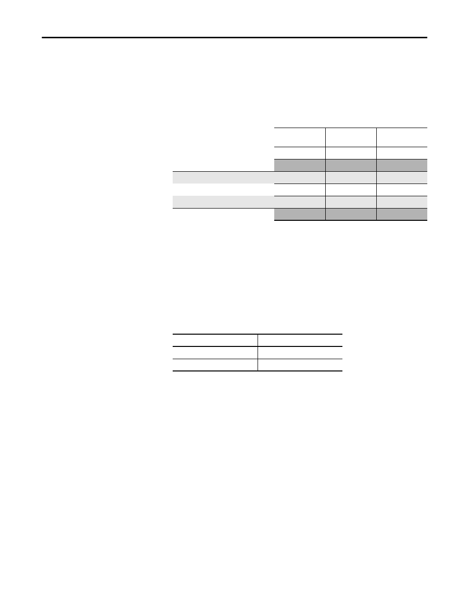
Feedback Voltage Monitoring Range
Use the [5V Monitoring] and [9V Monitoring] parameters to set the feedback
voltage monitoring range. The monitoring ranges help define the trip zone for
encoder 1 and encoder 2, respectively.
Table 17 - Feedback Voltage Monitoring Range
Your power supply must stay within the No Trip range.
Feedback Fault
The allowable frequency of feedback input signals is limited. The drive monitors
feedback signals whenever its configuration is valid and the Operation mode is
not configured as Disabled.
Table 18 - Maximum Encoder Frequency
If the feedback signals indicate greater-than or equal-to the maximum value, a
Feedback_
x fault (Safe State fault) occurs (x equals 1 or 2 depending upon the
encoder that has the fault).
Diagnostics are performed on the encoder input signals. If the encoder diagnostic
tests fail, a Feedback_
x fault (Safe State fault) occurs.
5/9V Monitoring
Setting
5
9
Range
4.5…5.5V
7…12V
Trip Zone
< 4.5V
< 7V
The encoder must be specified
Can Trip
4.5…4.62V
7…7.4V
to operate across this complete
No Trip
4.62…5.38V
7.4…11.4V
range or larger.
Can Trip
5.38…5.5V
11.4…12.0V
Trip Zone
>5.5V
> 12.0V
Encoder Type
Frequency, max
Sine/cosine
≤ 100 kHz
Incremental
≤ 200 kHz