Rockwell Automation 2094-EN02D-M01-S1 Kinetix 6200 and Kinetix 6500 Safe Speed Monitoring Safety Reference Manual User Manual
Page 31
Rockwell Automation Publication 2094-RM001C-EN-P - May 2013
31
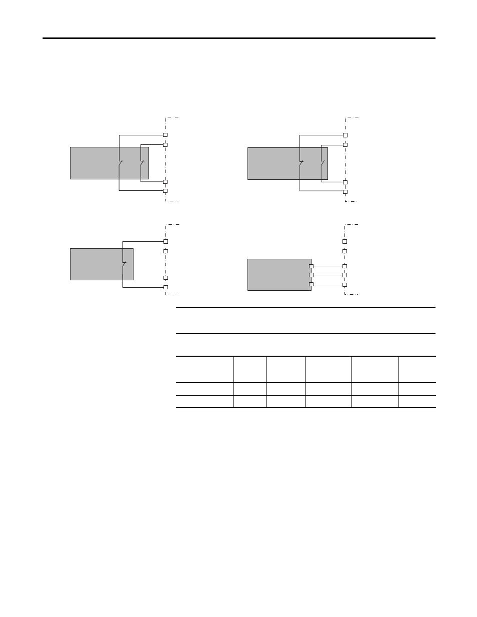
Speed Monitoring I/O Signals
Chapter 4
When using a dual-channel complementary device, the normally-open input
must be connected to the second input, as shown in the illustration. For example,
if the door is open when the input is ON, the normally-open contact must be the
second input (Input 1).
Figure 4 - Safety Input Wiring Examples
Table 3 - IOD Connector Input Terminals
Short-circuits of the input loop to ground or 24V are detected. For dual-channel
inputs, cross loops are also detected.
Test_Out_0 (IOD-27)
Test_Out_1 (IOD-28)
Dual-channel
Equivalent
Safety Device
Dual-channel
Complementary
Safety Device
Single
Channel
Safety Device
Solid State
Safety Device
Drive
N/C
N/C
Input 1
Input 0
GND
OSSD2
OSSD1
Drive
Drive
Drive
Input 1
Input 0
Input 1
Input 0
24V_COM (IOD-18)
Input 1
Input 0
Test_Out_0 (IOD-27)
Test_Out_1 (IOD-28)
Test_Out_0 (IOD-27)
Test_Out_1 (IOD-28)
Test_Out_0 (IOD-27)
Test_Out_1 (IOD-28)
IMPORTANT
Cross wiring of Test Outputs to Inputs is not allowed. For example, do not
connect TEST_OUT_0 to Input 1 or TEST_OUT_1 to Input 0.
Function
Safe Stop
(SS_In)
Safe Limited
Speed
(SLS_In)
Door Monitoring
(DM_In)
Enabling Switch
Monitoring
(ESM_In)
Lock
Monitoring
(LM_In)
Input 0 = Channel 0
IOD-19
IOD-23
IOD-31
IOD-37
IOD-33
Input 1 = Channel 1
IOD-20
IOD-24
IOD-32
IOD-38
IOD-34