Rockwell Automation 2094-EN02D-M01-S1 Kinetix 6200 and Kinetix 6500 Safe Speed Monitoring Safety Reference Manual User Manual
Page 122
122
Rockwell Automation Publication 2094-RM001C-EN-P - May 2013
Chapter 11
Safety Configuration Example
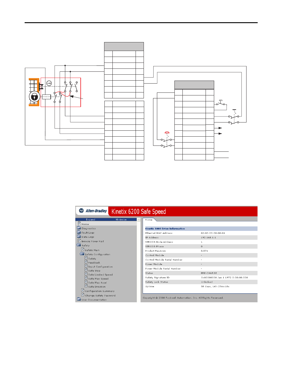
Figure 49 - Safe Limited Speed with Door Monitoring Example
(1) Lock monitoring connections are not required for Safe Limited Speed with Door Monitoring mode operation.
Each of the following sections describe the settings you need to enter for each
parameter group. Configuration is accomplished by using the safety
configuration tool.
Figure 50 - Safety Configuration Tool - Home Tab
12 22 34
11 21 33
A1
A2
42
41
52
51
GND
+24V DC
IOD Connector
27
28
27
28
27
28
27
28
27
28
27
28
27
28
27
28
TEST_OUT_0
TEST_OUT_1
TEST_OUT_0
TEST_OUT_1
TEST_OUT_0
TEST_OUT_1
TEST_OUT_0
TEST_OUT_1
SLS_OUT_CH0
SLS_OUT_CH1
DM_IN_CH0
DM_IN_CH1
LM_IN_CH0
LM_IN_CH1
DC_OUT_CH0
DC_OUT_CH1
ESM_IN_CH0
ESM_IN_CH1
29
30
31
32
33
34
35
36
37
38
29
30
31
32
33
34
35
36
37
38
IOD Connector
TEST_OUT_1
TEST_OUT_0
RESET_IN
RESET_REF
28
27
26
25
24
23
22
21
20
19
18
17
28
27
26
25
24
23
22
21
20
19
18
17
SLS_IN_CH1
SLS_IN_CH0
SS_OUT_CH1
SS_OUT_CH0
SS_IN_CH1
SS_IN_CH0
SCOM
SPWR
(1)
Kinetix 6200 and Kinetix 6500 Control Module
Safety Connections
IOD (44-pin) Connector
SLS
Request
SS
Request
Reset
Safe Stop
to Next Axis
(optional)
Remove (2)
Internal
Jumpers
TLS3 GD2
440G-T27260
Safety Switch
Power to
Release