Rockwell Automation 2094-EN02D-M01-S1 Kinetix 6200 and Kinetix 6500 Safe Speed Monitoring Safety Reference Manual User Manual
Page 58
58
Rockwell Automation Publication 2094-RM001C-EN-P - May 2013
Chapter 6
Safe Stop and Safe Stop with Door Monitoring Modes
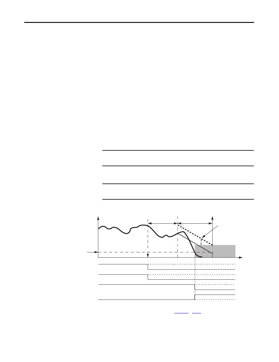
Deceleration monitoring takes place during the Stop Delay [Maximum Stop
Time]. These three configurable parameters define the deceleration profile that is
used:
• [Deceleration Reference Speed]
• [Deceleration Tolerance]
• Stop Delay, [Maximum Stop Time]
If Standstill Speed is detected any time after the Safe Stop has been initiated and
before the Stop Delay [Maximum Stop Time] expires, door control logic is set to
Unlock. If the Standstill Speed is not detected by the end of the configured Stop
Delay [Maximum Stop Time], a Stop Speed fault occurs.
When Safe Stop 1 is executed, the Guard Gate drive output is on (status = 1)
until standstill speed is reached or a fault occurs. This safe stop is commonly
known as a controlled, monitor stop.
For Safe Stop 1, motion power is removed when Standstill Speed is reached.
Figure 13 - Timing Diagram for Safe Stop 1
(1) This signal is internal to the drive.
(2) DC_Out output shown configured as Power to Release. See
for more information.
TIP
You can determine the drive/motor Stop Delay characteristics by using
Motion Analyzer software, version 4.7 or later.
IMPORTANT
Do not use Safe Stop 1 for vertical axis applications because the Guard Gate
output is off (status = 0) when below standstill speed.
IMPORTANT
For Safe Stop 1, after a successful SS_Reset, the Logix Designer application
must issue an MSF instruction prior to restarting the machine.
Stop Request
Stop Delay
Safe Torque-off
Active
Deceleration
Tolerance
Standstill Speed
Speed
Stop Monitoring
Delay
SS_Out Signal
SS_In Signal
Time
Motion Power
(1)
DC_Out Output
(2)