Power supply requirements, Wiring the safety connections, Figure 2 - making safety connections – Rockwell Automation 2094-EN02D-M01-S1 Kinetix 6200 and Kinetix 6500 Safe Speed Monitoring Safety Reference Manual User Manual
Page 26
26
Rockwell Automation Publication 2094-RM001C-EN-P - May 2013
Chapter 3
Installation and Wiring
Power Supply Requirements
The external power supply must conform to the Directive 2006/95/EC Low
Voltage, by applying the requirements of EN61131-2 Programmable Controllers,
Part 2 - Equipment Requirements and Tests and one of the following:
• EN60950 - SELV (Safety Extra Low Voltage)
• EN60204 - PELV (Protective Extra Low Voltage)
• IEC 60536 Safety Class III (SELV or PELV)
• UL 508 Limited Voltage Circuit
• 21.6…28.8V DC must be supplied by a power supply that complies with
IEC/EN60204 and IEC/EN 61558-1.
For planning information, refer to the guidelines in Industrial Automation
Wiring and Grounding Guidelines, Allen-Bradley publication
.
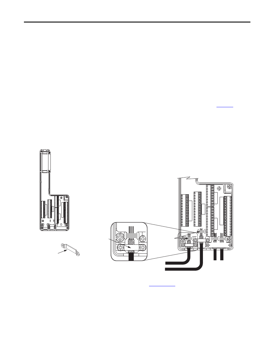
Wiring the Safety
Connections
Safety connections are made by using the 2090-K6CK-D44M low-profile
connector kit.
Figure 2 - Making Safety Connections
Refer to the Kinetix 6200 and Kinetix 6500 Modular Multi-axis Servo Drive
User Manual, publicat
, for safety, auxiliary feedback, and I/O
signal descriptions and wiring examples when using the 2090-K6CK-D44M
connector kit.
28 27 26 25 24 23 22 21 20 19 18 17 15 14 0
AUX FEEDBACK
0 11 10 9 8 7 6 5 4 3 2 1
0 39 41 40 39 42 40 39 43 40 39 44 40
INPUTS
0 38 37 36 35 34 33 32 31 30 29
28 27 28 27 28 27 28 27
S1 ONL
Y
S1 ONL
Y
S0&S1 W/S0 DISABLED
28 27 26 25 24 23 22 21 20 19 18 17 15 14 0
AUX FEEDBACK
0 11 10 9 8 7 6 5 4 3 2 1
0 39 41 40 39 42 40 39 43 40 39 44 40
INPUTS
0 38 37 36 35 34 33 32 31 30 29
28 27 28 27 28 27 28 27
S1 ONL
Y
S1 ONL
Y
S0&S1 W/S0 DISABLED
Clamp
2090-K6CK-D44M
Low-profile Connector Kit
Use tie wraps (4x)
for stress relief.
Turn clamps over for smaller
diameter cables.
Aux Feedback and I/O
Wires and Cables
Safety Wires
and Cables
Use shield clamps (3x) for
high-frequency bonding.
Kit pin numbering corresponds to the IOD
connector. Pins 27, 28, 39, and 40 are
given multiple terminals to
accommodate additional connections.