Rockwell Automation 2094-EN02D-M01-S1 Kinetix 6200 and Kinetix 6500 Safe Speed Monitoring Safety Reference Manual User Manual
Page 100
100
Rockwell Automation Publication 2094-RM001C-EN-P - May 2013
Chapter 8
Slave Modes for Multi-axis Cascaded Systems
Slave, Safe Limited Speed
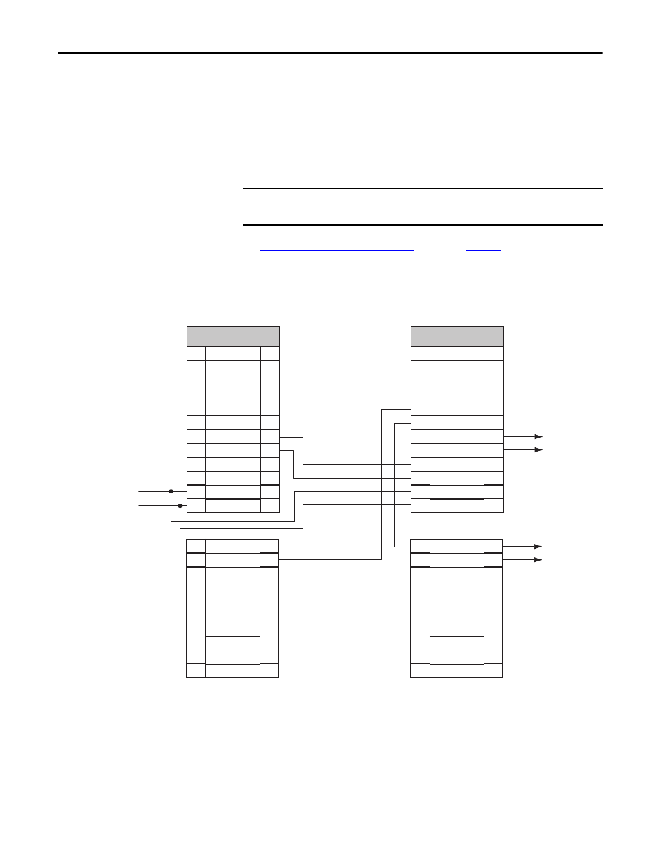
Status Only Wiring Examples
These examples show two different Slave, Safe Limited Speed Status Only
configurations.
The first example is configured as a cascaded middle unit via the [System
Configuration] parameter. It has SS_In, SLS_In, and DM_In input connections
from the previous upstream drive, as well as SS_Out, SLS_Out, and DC_Out
output connections to the next downstream drive.
See
SLS Status Only Wiring Examples
for an example of a
first (master) unit.
Figure 34 - Slave, Safe Limited Speed Status Only, Middle Drive
IMPORTANT
The SLS_Out signals change state immediately based on the speed relative to
the Safe Speed Limit if the Safe Limited Speed Monitoring Delay is set to zero.
+24V DC
GND
SLS_OUT_CH0
SLS_OUT_CH1
DM_IN_CH0
DM_IN_CH1
LM_IN_CH0
LM_IN_CH1
DC_OUT_CH0
DC_OUT_CH1
ESM_IN_CH0
ESM_IN_CH1
29
30
31
32
33
34
35
36
37
38
29
30
31
32
33
34
35
36
37
38
IOD Connector
TEST_OUT_1
TEST_OUT_0
RESET_IN
RESET_REF
28
27
26
25
24
23
22
21
20
19
18
17
28
27
26
25
24
23
22
21
20
19
18
17
SLS_IN_CH1
SLS_IN_CH0
SS_OUT_CH1
SS_OUT_CH0
SS_IN_CH1
SS_IN_CH0
SCOM
SPWR
Previous Upstream Axis
IOD Connector Terminals
Next Downstream Axis
IOD Connector Terminals
Safe Stop
to Next Axis
SLS to
Next Axis