Wiring examples, Figure 9 - estop figure 10 - safety gate – Rockwell Automation 1752-L24BBBE SmartGuard 600 Controllers User Manual User Manual
Page 37
Rockwell Automation Publication 1752-UM001E-EN-P - June 2014
37
Installing and Wiring the SmartGuard 600 Controller
Chapter 2
Wiring Examples
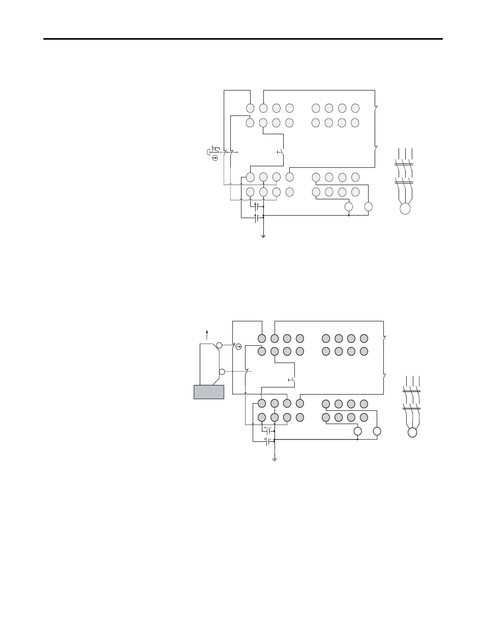
Figure 9 - ESTOP
Figure 10 - Safety Gate
V1
G1 T
0
T1
I1
I0
I3
I5
I2
I4
I6
I7
T2
T3
E1
S1
11 21
12 22
O1
O0
V2 G
2
O3 O5
O2 O4 O6
O7
E2
KM 1
KM 2
I9
I8
I1 1
I1 3
I1 0
I1 2
I1 4
I1 5
KM 1 - N C
KM 2 - N C
M
KM1
KM2
S2
E1 and E2: 24V dc Power Supplies
S1: Emergency Stop Switch
S2: Reset Switch (N.O. Contact)
KM1 and KM2: Contactors
Connect a 24V dc power supply to terminals V0 and G0, the power supply terminals for internal circuits.
V1
G1
T0
T1
I1
I0
I3
I5
I2
I4
I6
I7
T2
T3
E1
S1
O1
O0
V2
G2
O3
O5
O2
O4
O6
O7
E2
KM1
KM2
KM1
KM2
I9
I8
I11
I13
I10
I12
I14
I15
KM1-NC
KM2-NC
S3
M
Connect a 24V dc power supply to terminals V0 and G0, the power supply terminals for internal circuits.
Open
E1 and E2: 24V dc Power Supplies
S1: Limit Switch 1
S2: Limit Switch 2
S3: Reset Switch
KM1 and KM2: Contactors