F - application and configuration examples, Introduction, Emergency stop application – Rockwell Automation 1752-L24BBBE SmartGuard 600 Controllers User Manual User Manual
Page 271: Appendix f, Application and configuration examples, Introduction emergency stop application, Appendix
Rockwell Automation Publication 1752-UM001E-EN-P - June 2014
271
Appendix
F
Application and Configuration Examples
Introduction
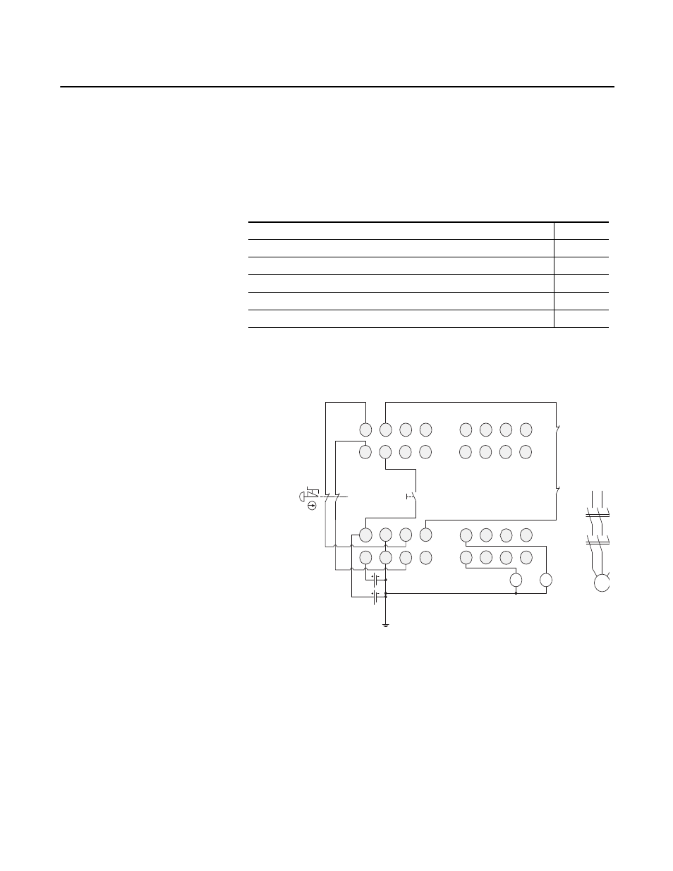
Emergency Stop Application
This example shows a dual channel emergency stop switch with manual reset.
Figure 91 - Emergency Stop Wiring Diagram
Topic
Page
Safety Gate Application with Automatic Reset
Dual Zone Safety Gate Application Using Emergency Stop Switch with Manual Reset
V1
G1 T
0
T1
I1
I0
I3
I5
I2
I4
I6
I7
T2
T3
E1
S1
11 21
12 22
O1
O0
V2 G
2
O3 O5
O2 O4 O6
O7
E2
KM 1
KM 2
I9
I8
I1 1
I1 3
I1 0
I1 2
I1 4
I1 5
KM 1 - N C
KM 2 - N C
M
KM1
KM2
S2
E1 and E2: 24V dc Power Supplies
S1: Emergency Stop Switch
S2: Reset Switch (N.O. Contact)
KM1 and KM2: Contactors
Connect a 24V dc power supply to terminals V0 and G0, the power supply terminals for internal circuits.