Rockwell Automation 1752-L24BBBE SmartGuard 600 Controllers User Manual User Manual
Page 35
Rockwell Automation Publication 1752-UM001E-EN-P - June 2014
35
Installing and Wiring the SmartGuard 600 Controller
Chapter 2
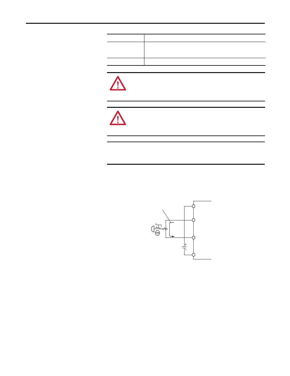
When safety devices are connected via test outputs to an input circuit on the
SmartGuard controller, we recommend the length of the wire to be 30 m (98.4 ft)
or less.
Figure 6 - Input Devices with Mechanical Contact Outputs
Devices, such as light curtains, with current-sourcing PNP semiconductor
outputs send a signal to the SmartGuard 600 controller safety input terminal and
do not use a test output.
IN0…IN15
Terminals for safety inputs.
T0…T3
These are test output terminals that can provide pulse test sources for safety inputs
IN0…IN15. T3 can also support wire off detection and burned out bulb detection for a
load such as a muting lamp.
OUT0…OUT7
Terminals for safety outputs.
ATTENTION: If you connect or disconnect wiring while the field-side power is
applied, an electrical arc can occur. This could cause an explosion in hazardous
location installations. Be sure that power is removed or the area is
nonhazardous before proceeding.
ATTENTION: If you connect or disconnect the removable terminal block (RTB)
while the field-side power is applied, an electrical arc can occur. This could
cause an explosion in hazardous location installations. Be sure that power is
removed or the area is nonhazardous before proceeding.
IMPORTANT
Prepare stranded wires by attaching ferrules with plastic insulation covers
(compliant with the DIN 46228-4 standard). Ferrules similar in appearance but
not compliant may not match the terminal block on the controller.
SmartGuard 600
Controller
V1
Tx
INx
G1
24V dc
4.5 mA Typical