User mode switch function block timing chart, External device monitoring (edm), Edm function block optional outputs – Rockwell Automation 1752-L24BBBE SmartGuard 600 Controllers User Manual User Manual
Page 236
236
Rockwell Automation Publication 1752-UM001E-EN-P - June 2014
Appendix D
Function Blocks Command Reference
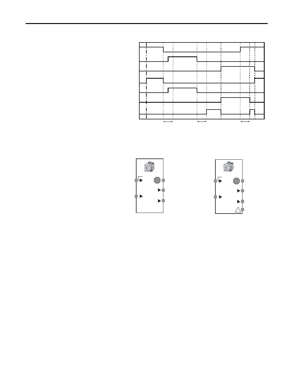
User Mode Switch Function Block Timing Chart
External Device Monitoring
(EDM)
Figure 60 - External Device Monitoring Function Block Diagram
The External Device Monitoring (EDM) function block evaluates the
Monitored Input signal and the status of an external device feedback signal
(EDM Feedback) and then turns on safety outputs to an external device.
If the Monitored Input signal turns on, the Output 1 and Output 2 signals turn
on. When this occurs, the status of the feedback signal must change within the
specified time. If the Monitored Input signal turns off, the Output 1 and Output
2 signals turn off. When this occurs, the status of the feedback signal must change
within the specified time.
If the status of the feedback signal does not change within the specified time, an
EDM error occurs, the Output 1 and Output 2 signals turn off, and the EDM
error signal turns on.
EDM Function Block Optional Outputs
Optional outputs can also be used in programming. To use these optional
outputs, check the appropriate checkbox on the Out point tab of the Function
Input 1
Idle to RUN
Input 2
Input 3
Output 1
Output 2
Output 3
2 seconds
2 seconds
2 seconds
Fault Present
!
!
!
EDM Feedback
Output 1
Monitored
Input
Default Connections
Maximum I/O for EDM Function
Output 2
EDM Error
EDM Feedback
Output 1
Monitored Input
Output 2
EDM Error
Fault Present