Rockwell Automation 1752-L24BBBE SmartGuard 600 Controllers User Manual User Manual
Page 247
Rockwell Automation Publication 1752-UM001E-EN-P - June 2014
247
Function Blocks Command Reference
Appendix D
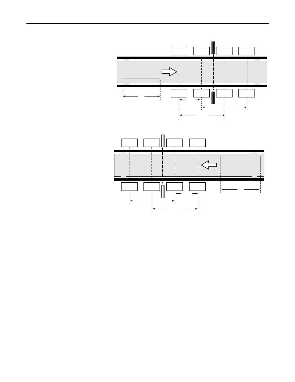
Figure 68 - Application Setup
Sensor 11 is connected to Muting Signal 11. Sensor 12 is connected to Muting
Signal 12. Sensor 21 is connected to Muting Signal 21. Sensor 22 is connected to
Muting Signal 22.
Muting Sequence
The muting sequence for this example is described below.
1.
The light is not interrupted between sensors 11, 12, 21, and 22 and the
light curtain, so the Output Enable signal is on.
2.
For the entrance, as the workpiece moves to the right and sensors 11 and
12 go on in order (sensors 21 and 22 go on as the workpiece exits), muting
is enabled and the muting signal turns on.
3.
As the workpiece continues to advance, the Output Enable signal is kept
on even if the light curtain is obstructed.
4.
As the workpiece continues to advance, the workpiece is no longer
detected by sensor 21 at the entrance (sensor 12 during workpiece exit),
the muting status is cleared, and the muting signal turns off.
Sensor 11
Workpiece
L
V
Sensor 11
Sensor 12
Sensor 12
Sensor 21
Sensor 21
Sensor 22
Sensor 22
d2
D3
D2
Entrance
Sensor 11
Workpiece
L
V
Sensor 11
Sensor 12
Sensor 12
Sensor 21
Sensor 21
Sensor 22
Sensor 22
d2
D3
D2
Exit
Light Curtain
Light Curtain