Muting function block parameters, Muting function block optional outputs – Rockwell Automation 1752-L24BBBE SmartGuard 600 Controllers User Manual User Manual
Page 239
Rockwell Automation Publication 1752-UM001E-EN-P - June 2014
239
Function Blocks Command Reference
Appendix D
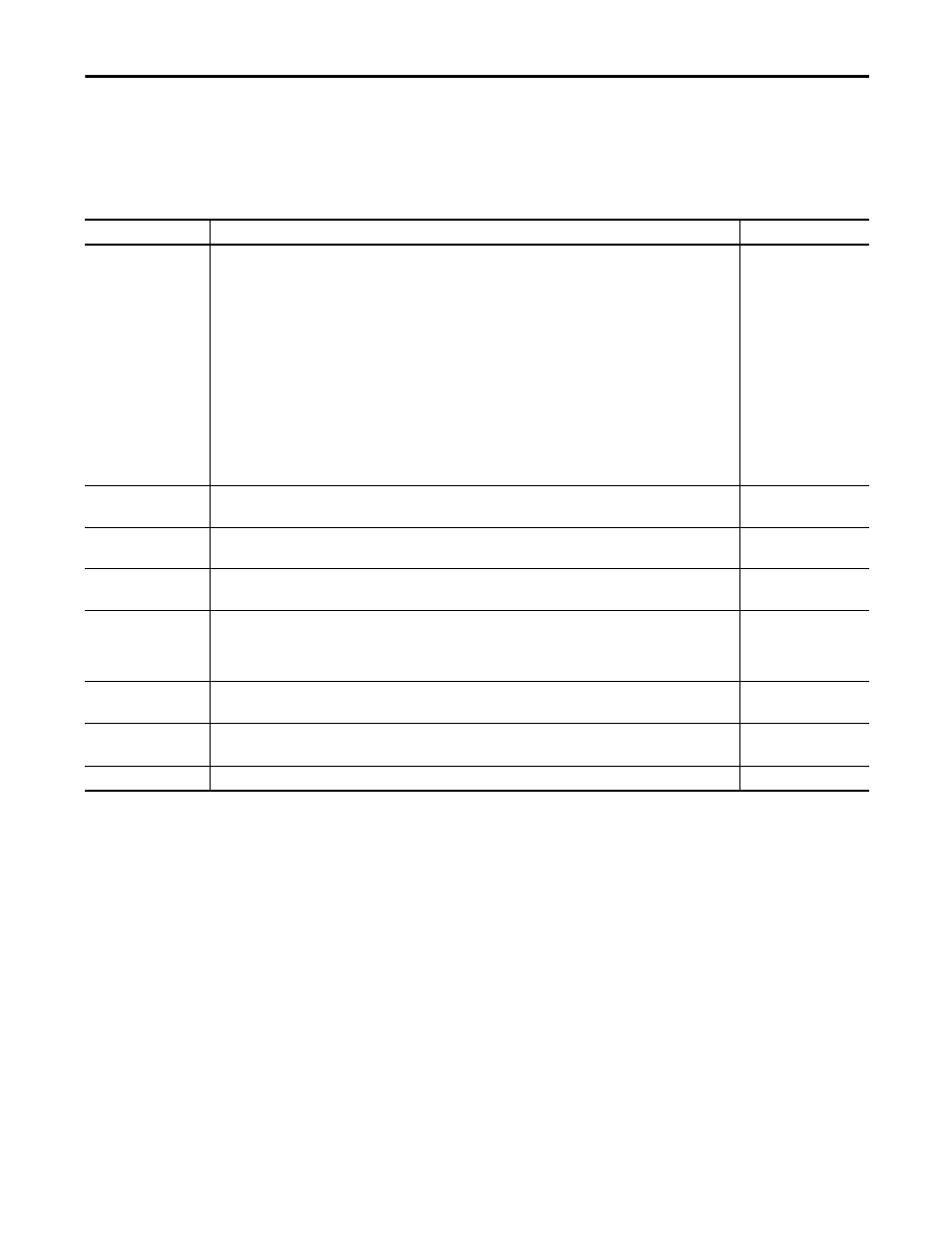
Muting Function Block Parameters
Set these parameters for the two-hand control function block.
Muting Function Block Optional Outputs
Optional outputs can also be used in programming. To use these optional
outputs, check the appropriate checkbox on the In/Out Setting tab of the
Function Block Properties dialog box in the Logic Editor of RSNetWorx for
DeviceNet software.
•
Overriding
•
Synchronization error
•
Sequence error
•
Discrepancy error (AOPD)
•
Discrepancy error (Override)
Table 28 - Muting Function Block Parameters
Parameter
Settings/Range
Default
Muting Mode
·Parallel muting with 2 sensors
This pattern is suitable for applications at a conveyor entrance. Use this pattern when two retro-reflective photoelectric
sensors are set up as muting sensors with intersecting detection zones.
·Sequential muting (forward direction)
This pattern is suitable for applications at a conveyor entrance. Use this pattern when four through-beam photoelectric
sensors are set up as muting sensors.
·Sequential muting (both directions)
This pattern is suitable for applications at a conveyor entrance or exit. Use this pattern when four through-beam
photoelectric sensors are set up as muting sensors.
·Position detection
This pattern is suitable for applications in which muting is controlled by a switch input. Use this pattern to temporarily
disable the light-interruption signal of the light curtain when an operator is placing an object in the machine opening,
and the machine is in a state where it will not harm the operator (hazards are in a different zone of the machine).
In all of these setting explanations, the muting sensors are on when detection is performed and off when detection is not
performed.
Parallel muting with 2
sensors
Synchronization Time
(1)
30 ms…3 seconds in 10 ms increments.
The timer SV must be longer than the controller’s cycle time.
3 seconds
Input Type of AOPD
·Dual Channel Equivalent (NC/NC)
·Dual Channel Complementary (NC/NO)
Dual Channel Equivalent
Discrepancy Time (AOPD)
10…500 ms in 10 ms increments
(2)
The timer SV must be longer than the controller’s cycle time.
30 ms
Input Type of Override
Signal
·Single Channel
·Dual Channel Equivalent (NO/NO)
·Dual Channel Complementary (NC/NO)
·Not Used
Not used
Discrepancy Time
(Override)
10…500 ms in 10 ms increments
(2)
The timer SV must be longer than the controller’s cycle time.
30 ms
Max Muting Time
500 ms…127.5 seconds in 500 ms increments
0…500 ms in 10 ms increments
60 seconds
Max Override Time
500 ms…127.5 seconds in 500 ms increments
60 seconds
(1) Between Muting Signal 11 and Muting Signal 12 or between Muting Signal 21 and Muting Signal 22.
(2) A discrepancy time check will not be performed is 0 is set.