Rockwell Automation 1752-L24BBBE SmartGuard 600 Controllers User Manual User Manual
Page 196
196
Rockwell Automation Publication 1752-UM001E-EN-P - June 2014
Appendix B
Status Indicators
If your Module Status indicator is solid red (on), follow these steps.
1.
Cycle the power supply.
2.
Check external wiring.
3.
Take corrective actions for noise.
4.
Contact Rockwell Automation.
If your Module Status indicator is flashing red and green, follow these steps.
1.
Configure the switches properly.
2.
Set the safety network number.
3.
Reconfigure the device.
If your Network Status indicator is off, follow these steps.
1.
Cycle the power supply.
2.
Check external wiring.
3.
Take corrective actions for noise.
4.
Contact Rockwell Automation.
If your Network Status indicator is on or flashing red, follow these steps.
1.
View the Alphanumeric display for the node address of the error and error
code.
2.
Check that node addresses have not been duplicated.
3.
Make sure the communication rate is the same for all nodes.
4.
Check that cables are not loose, disconnected or too long.
5.
Verify that terminating resistors have been installed only at both ends of
the main line.
6.
Take corrective action for noise.
7.
Make sure target devices are configured, verified, and in normal operating
state.
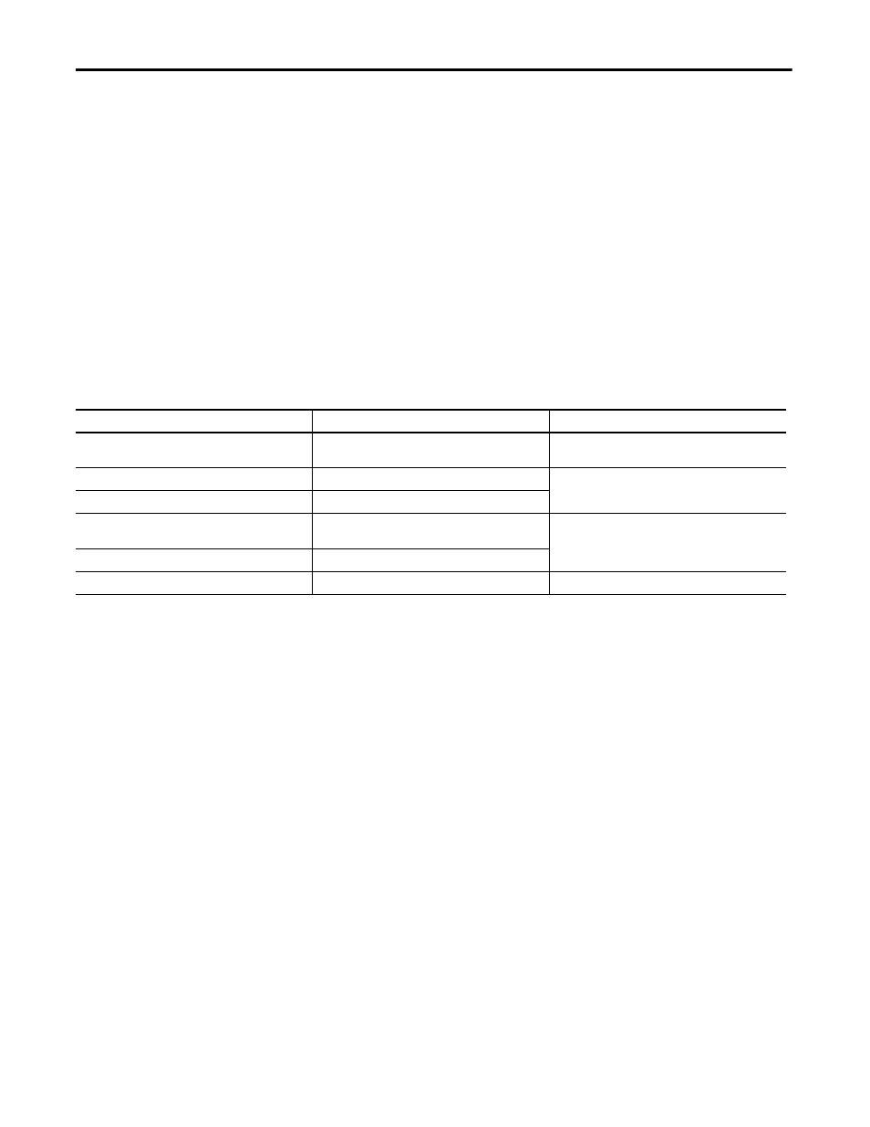
If the DeviceNet Network Status (NS D) indicator is
It means
Take this action
Off
The controller is not online or may not have power from
the DeviceNet network.
Refer to the corrective action following this table.
Green, on
The controller is online; connections are established.
No action required.
Green, flashing
The controller is online; no connections are established.
Red, on
Communication failure due to duplicate MAC ID (error
code F0) or Bus OFF (error code F1).
Refer to the corrective action following this table.
Red, flashing
Communication timeout.
Red/green flashing
The Safety Network Number (SNN) is being set.
No action required.