Rockwell Automation 1752-L24BBBE SmartGuard 600 Controllers User Manual User Manual
Page 199
Rockwell Automation Publication 1752-UM001E-EN-P - June 2014
199
Status Indicators
Appendix B
Identifying Errors Using
Module Status Indicators and
Alphanumeric Display
Use these tables to interpret the color and status combinations of the status and
alphanumeric display indicators and take corrective action where applicable.
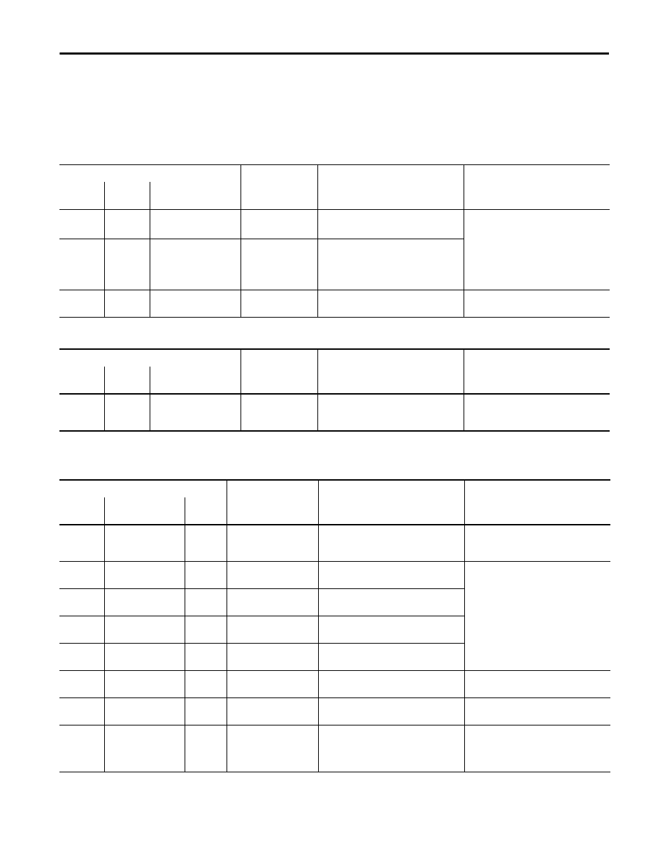
Table 30 - Critical Errors
Indicators
Error Log
Cause
Corrective Action
MS
NS
Alphanumeric Display
Code
Off
Off
Off
None
Critical hardware fault.
Noise level higher than expected.
1. Cycle the power supply.
2. Check external wiring.
3. Take corrective actions for noise.
4. Contact Rockwell Automation.
Red, on
Off
Left: H
Right: ---
System Failure
Critical hardware fault.
Noise level higher than expected.
Output terminal shorted to 24V dc before
operation.
Red, on
Off
P6
System Failure
Output terminal shorted to 24V dc before
operation.
1. Cycle the power supply.
2. Check external wiring.
Table 31 - Abort Error
Indicators
Error Log
Cause
Corrective Action
MS
NS
Alphanumeric Display
(1)
Code
Red,
flashing
Green, on or
flashing
E8
Switch setting
mismatch
The node address and baud rate were
changed after the normal completion of
configuration download.
1. Set switches properly.
2. Reconfigure the device.
(1) Display alternates between error code and node address of the error.
Table 32 - Nonfatal Errors
Indicators
Error Log
Cause
Corrective Action
MS
Alphanumeric
Display
(1)
Code
I/O
Red, on
F0
---
Duplicate MAC ID
The same node address is set for more than
one node.
Check that node addresses have not been
duplicated and reconfigure the device if
necessary.
Red, on
F1
---
Bus Off
Communication is cut off because of frequent
data errors.
1. Make sure the communication rate is the
same for all nodes.
2. Check that cables are not loose,
disconnected, or too long.
3. Verify that terminating resistors have been
installed only at both ends of the main
line.
4. Take corrective action for noise.
5. Cycle the power supply.
Red,
flashing
L9
---
Standard I/O Connection
Timeout
Standard I/O connection timeout.
Red,
flashing
dA
---
Safety I/O Connection
Timeout
Safety I/O connection timeout.
Red,
flashing
d5
---
Nonexistent Slave Device
No slave detected.
Red,
flashing
d6
---
Safety I/O Connection
Establishment Failure
Safety I/O connection could not be
established.
Make sure the slave device is configured and
in a normal operational state.
Red,
flashing
d6
---
Invalid Slave Device
Invalid slave device due to verification error.
1. Verify the slave device’s configuration.
2. Connect a compatible slave device.
Off
E0
---
Network PS Voltage Low
Network power supply voltage is low.
1. Make sure the power supply voltage is set
within the specified range.
2. Check that cables or wires are not loose or
disconnected.