Wire output devices – Rockwell Automation 1752-L24BBBE SmartGuard 600 Controllers User Manual User Manual
Page 36
36
Rockwell Automation Publication 1752-UM001E-EN-P - June 2014
Chapter 2
Installing and Wiring the SmartGuard 600 Controller
Figure 7 - Input Devices with PNP Semiconductor Outputs
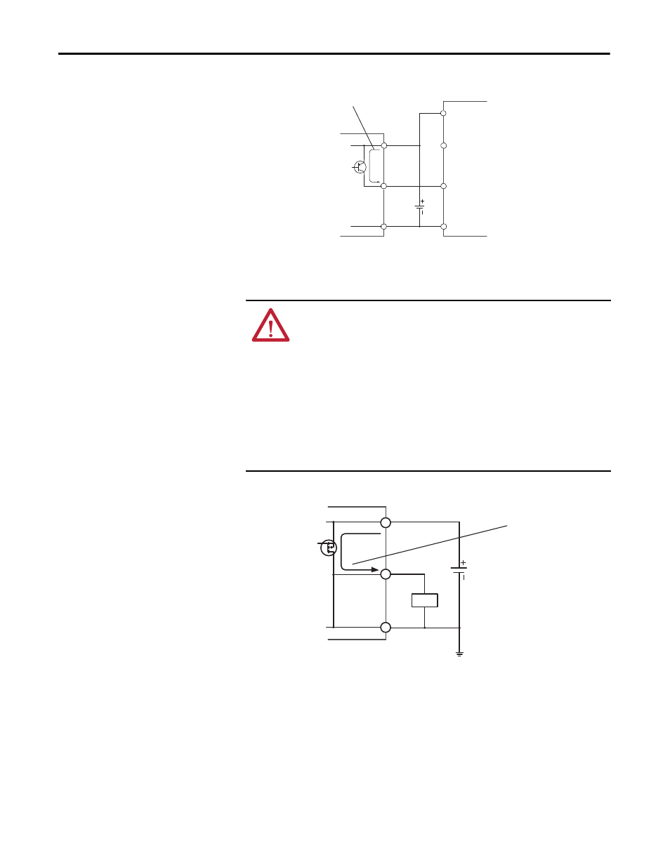
Wire Output Devices
Figure 8 - Output Device Wiring
ATTENTION: Serious injury may occur due to a loss of required safety functions.
Do not connect loads beyond the rated value of safety or test outputs.
Do not use test outputs as safety outputs.
Wire the controller properly so that the 24V dc lines do not touch the safety or test
outputs.
Do not apply the power supply to the test output terminals.
Ground the 0V line of the power supply for external output devices so that the
devices do not turn on when the safety output line or the test output line is
grounded.
Separate I/O cables from high voltage or high current lines.
SmartGuard 600
Controller
V1
Tx
INx
G1
24V dc
24V dc
OSSDx
GND
4.5 mA Typical
SmartGuard 600
Controller
V2
G2
24V dc
OUTx
0.5 A Max
Load