1 configuring the can interface – Lenze PLC Designer V2.x User Manual
Page 35
1.3 EN - 07/2012
L
35
PLC Designer V2.x| Lenze Application Samples
Commissioning a sample project
Wiring the hardware
7.2.1
Configuring the CAN interface
For the configuration of the CAN interface the different hardware
(Industrial PC and EL1xx) is to be observed.
Industrial PC
In the case of the Industrial PC you configure the CAN bus using the »PLC Designer«.
EL1xx
In the case of the EL1xx, the device, and additionally the CAN bus must be configured
in the »PLC Designer«.
How to proceed in the case of the EL1xx:
1. On the EL 1xx, click StartSettingsControl PanelFieldbus
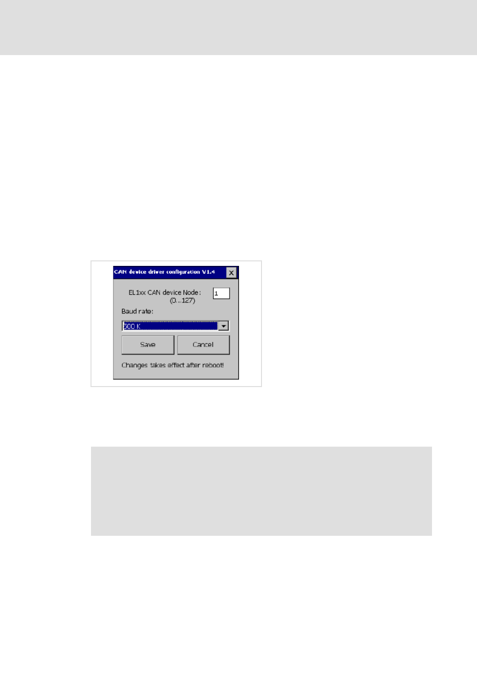
2. Configure the CAN interface in the following dialog window:
3. Click the Save button to save the settings.
Since the »PLC Designer« accesses the Industrial PC or the EL1xx via Ethernet, connect the
Industrial PC or the EL1xx device to your Engineering PC via a network cable.
EL 1xx CAN device node: node address
of the EL 1xx within a CAN network.
Baud rate: transmission speed of the
fieldbus. The baud rate must be
identical for each fieldbus node within
a network.
According to the baud rate, the
fieldbus parameters are set.
Note!
• During initial commissioning, observe the following predefined IP addresses:
– Engineering PC: 192.168.5.100
– Industrial PC: 192.168.5.99
• The network setting for the EL1xx is set to DHCP and has to be set to a fixed
IP address first, so that communication is possible.