Structure of, Plc designer v2.x| lenze application samples – Lenze PLC Designer V2.x User Manual
Page 277
1.3 EN - 07/2012
L
277
PLC Designer V2.x| Lenze Application Samples
The L_S93_Drive9300.lib library
L_S93_ActuatorSpeed - control the 9300 Speed
16.1.1
Structure of 93_DriveControl_Speed - actuation to the controller
Further information on the interface assignments can be found in the following section:
Interface assignment in the »Global Drive Control«
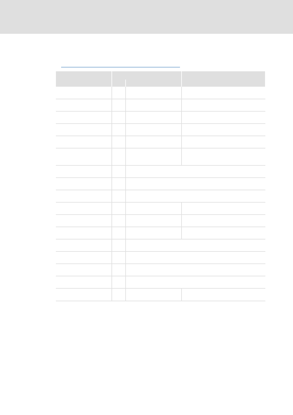
Identifier/data type
Control bits in the controller
Bit
Designation
Meaning
xJog1
BOOL
0
CAN-CTRL.B0
Activate manual jog in positive direction
(clockwise)
xJog2
BOOL
1
CAN-CTRL.B1
Activate manual jog in negative direction
(counter-clockwise)
xCcw
BOOL
2
CAN-CTRL.B2
Define direction of rotation of the motor
xQSP
BOOL
3
CAN-CTRL.B3
Activate quick stop
xNSet_RfgStop
BOOL
4
CAN-CTRL.B4
Stop ramp function generator
xNSet_Rfg0
BOOL
5
CAN-CTRL.B5
Ramp function generator input = 0
• RFG1 = ramp function generator of main
setpoint
xFreeBit06
BOOL
6
Not assigned
xFreeBit07
BOOL
7
Not assigned
xCtrl_Disable
BOOL
8
Not used
xEnable
BOOL
9
CAN-CTRL.B9
Activate FB
xErrorSet
BOOL
10
CAN-CTRL.B10
Set error
xErrorReset
BOOL
11
CAN-CTRL.B11
Reset error
xFreeBit12
BOOL
12
Not assigned
xFreeBit13
BOOL
13
Not assigned
xFreeBit14
BOOL
14
Not assigned
xFreeBit15
BOOL
15
Not assigned
rNSet
REAL
Speed setpoint