Agilent Technologies N9010A User Manual
Page 47
Chapter 1
47
Agilent EXA Signal Analyzer
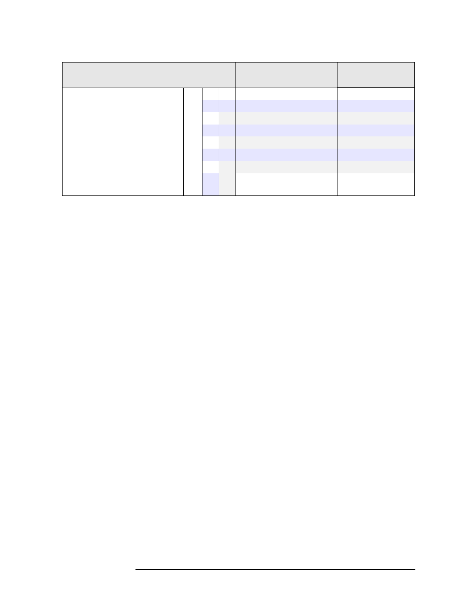
Dynamic Range
22 to 26.5 GHz
x
−134 dBm
−130 dBm
−140 dBm
20 to 26.5 GHz
x
−139 dBm
−137 dBm
−143 dBm
20 to 26.5 GHz
x
−142 dBm
−140 dBm
−145 dBm
26.4 to 34 GHz
x
−137 dBm
−133 dBm
−142 dBm
26.4 to 34 GHz
x
−140 dBm
−136 dBm
−144 dBm
33.9 to 44 GHz
x
−131 dBm
−127 dBm
−137 dBm
33.9 to 44 GHz
x
−135 dBm
−131 dBm
−140 dBm
Additional DANL, IF Gain=Low
c
x
x
x
−160.5 dBm
(nominal)
a. DANL for zero span and swept is measured in a 1 kHz RBW and normalized to the narrowest available
RBW, because the noise figure does not depend on RBW and 1 kHz measurements are faster.
b. DANL below 10 MHz is affected by phase noise around the LO feedthrough signal. Specifications
apply with the best setting of the Phase Noise Optimization control, which is to choose the “Best
Close-in
φ Noise" for frequencies below 25 kHz, and “Best Wide Offset φ Noise" for frequencies above
25 kHz.
c. Setting the IF Gain to Low is often desirable in order to allow higher power into the mixer without
overload, better compression and better third-order intermodulation. When the Swept IF Gain is set to
Low, either by auto coupling or manual coupling, there is noise added above that specified in this table
for the IF Gain = High case. That excess noise appears as an additional noise at the input mixer. This
level has sub-decibel dependence on center frequency. To find the total displayed average noise at the
mixer for Swept IF Gain = Low, sum the powers of the DANL for IF Gain = High with this additional
DANL. To do that summation, compute DANLtotal = 10
× log (10^(DANLhigh/10) + 10^(Additional-
DANL / 10)). In FFT sweeps, the same behavior occurs, except that FFT IF Gain can be set to autor-
ange, where it varies with the input signal level, in addition to forced High and Low settings.
Description
Specifications
Supplemental
Information