Example, Output mode, Utput – EVS IPDirector Version 4.3 - October 2007 Part 3 User's Manual User Manual
Page 195
Issue 4.3.C
IP Director Version 4.3 – User Manual – Part 3: Ingest and Play-Out
EVS Broadcast Equipment
182
have been assigned to the Remote via the Replace function
defined on the Remote itself.
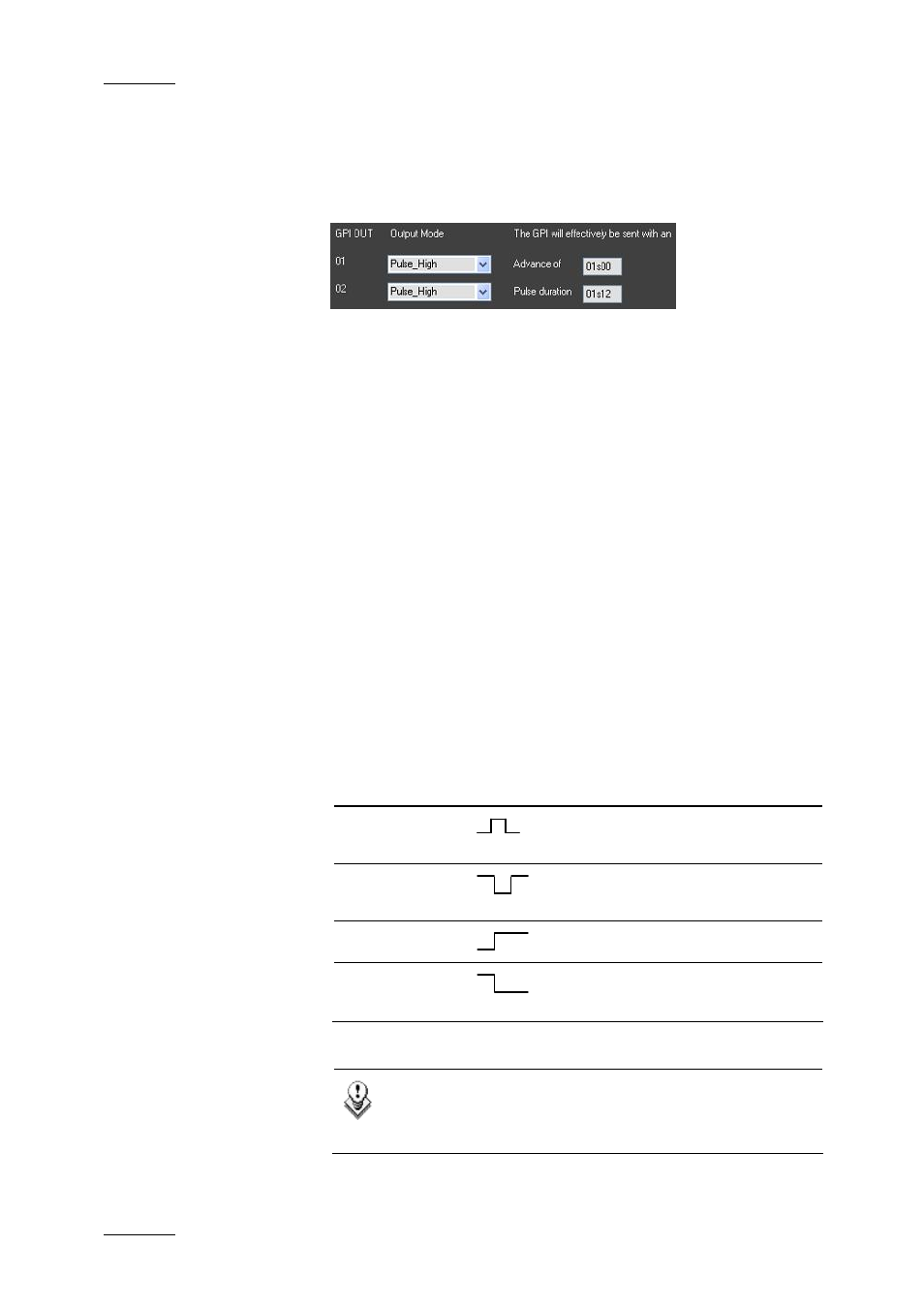
Example
We consider that a GPI tag has been defined on the GPI key 1 in
the Play-List Editor on a given timecode of a play-list. In the
above configuration, a high pulse signal, that will last 1.12 sec.
(Pulse Duration value), will be sent to the GPI key 1 just 1 sec.
(Advance value) before the given timecode is reached in the
play-list. This signal can be handled by a third device, e.g. a
VTR, to trigger a record action on this device, for example. If the
VTR is properly set up, it could start recording the play-list from
the XT server on the given timecode.
For more information on how to define GPI tags in the Play-List
Editor, refer to section ‘Insert Tag’, on page 146 in the Play-List
Editor chapter.
The following sections describe in details the various fields in
the OUTPUT GPI Configuration pane:
O
UTPUT
M
ODE
The output mode field allows the user to define the type of signal
that the GPI key will have to send to the third device. The
following output modes can be defined:
Trigger Mode
Description
Pulse Rising
Edge
The GPI signal will be a rising
edge pulse.
Pulse Falling
Edge
The GPI signal will be a falling
edge pulse.
Level High
The output level is set to high.
Level Low
The output level is set to low.
Note
When you define a pulse signal, you also need to
specify the pulse duration.