Trigger mode, Delay, 5 output gpi configuration pane – EVS IPDirector Version 4.3 - October 2007 Part 3 User's Manual User Manual
Page 194: Output gpi configuration pane, 5 output, Onfiguration
IP Director Version 4.3 – User Manual – Part 3: Ingest and Play-Out
EVS Broadcast Equipment
Issue 4.3.C
181
T
RIGGER
M
ODE
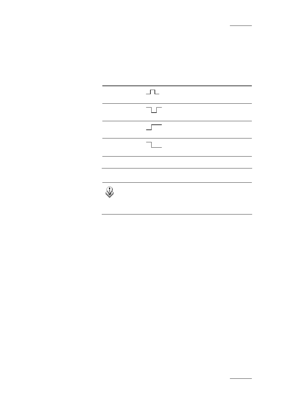
The trigger mode field allows the user to define the type of
trigger signal that will be sent by the GPI to the XT server. The
following trigger modes can be defined:
Trigger Mode
Description
Pulse Rising
Edge
The trigger is done on a rising
edge pulse.
Pulse Falling
Edge
The trigger is done on a falling
edge pulse.
Level High
The trigger is done when the level
changes to high level
Level Low
The trigger is done when the level
changes to low level
None
No trigger mode is defined.
Note
If the operator selects ‘None’ for one of the fields, all
three fields are reset to ‘None’. It is considered that the
GPI is not used.
D
ELAY
It is possible to specify a delay between the time the GPI key is
pressed and the time the action will be carried out on the XT
server.
6.10.5 OUTPUT
GPI
C
ONFIGURATION
P
ANE
The OUTPUT GPIs are signals that are sent by the GPI from an
XT server under the control of the IP Director. Four GPI OUT
commands can be sent from an XT server.
The OUTPUT GPIs settings are used to send a signal from the IP
Director to a GPI key at a given timecode of a play-list played on
a given player channel. This signal can then be used to trigger a
record action of the play-list from the given timecode by a third
device, for example a VTR.
For each OUTPUT GPI, the output mode can be set and a
general setting can determine the pulse width and timing.
The OUTPUT GPI keys will be greyed-out in IP Director if they