4 accessing high registers in thumb state, Figure 2-5, Arm architecture reference manual – Epson ARM.POWERED ARM720T User Manual
Page 47: For details on high register operations
2: Programmer’s Model
ARM720T CORE CPU MANUAL
EPSON
2-7
2.6.3
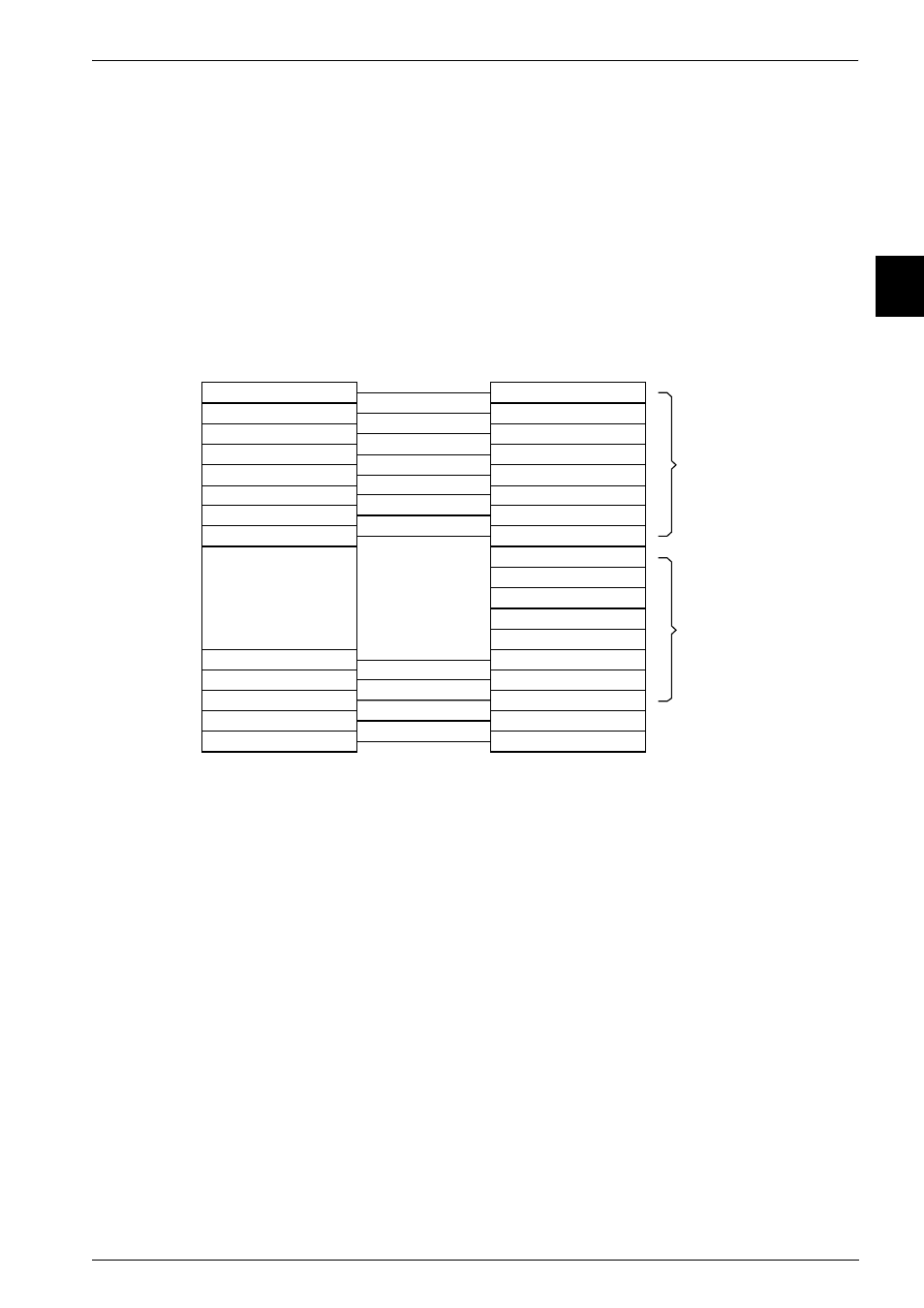
The relationship between ARM and Thumb state registers
The Thumb state registers relate to the ARM state registers in the following ways:
•
Thumb state r0–r7, and ARM state r0–r7 are identical
•
Thumb state CPSR and SPSRs, and ARM state CPSR and SPSRs are identical
•
Thumb state SP maps onto ARM state r13
•
Thumb state LR maps onto ARM state r14
•
Thumb state PC maps onto ARM state PC (r15).
This relationship is shown in Figure 2-5.
Figure 2-5 Mapping of Thumb state registers onto ARM state registers
2.6.4
Accessing high registers in Thumb state
In Thumb state, ARM registers r8–r15 (the high registers) are not part of the standard
register set. However, the assembly language programmer has limited access to them, and can
use them for fast temporary storage.
A value can be transferred from a register in the range r0 – r7 (a
low register) to a high
register, and from a high register to a low register, using special variants of the MOV
instruction. High register values can also be compared against or added to low register values
with the CMP and ADD instructions. See the
ARM Architecture Reference Manual
for details
on high register operations.
Thum b s tate
ARM s tate
r0
r1
r2
r3
r4
r5
r6
r7
SP
LR
CPSR
SPSR
r0
r1
r2
r3
r4
r5
r6
r7
r8
SP (r13)
LR (r14)
CPSR
SPSR
r9
r10
r11
r12
PC
PC (r15)
Low
registers
High
registers