Figure 9-12, Embeddedice-rt block diagram -34 – Epson ARM.POWERED ARM720T User Manual
Page 166
9: Debugging Your System
9-34
EPSON
ARM720T CORE CPU MANUAL
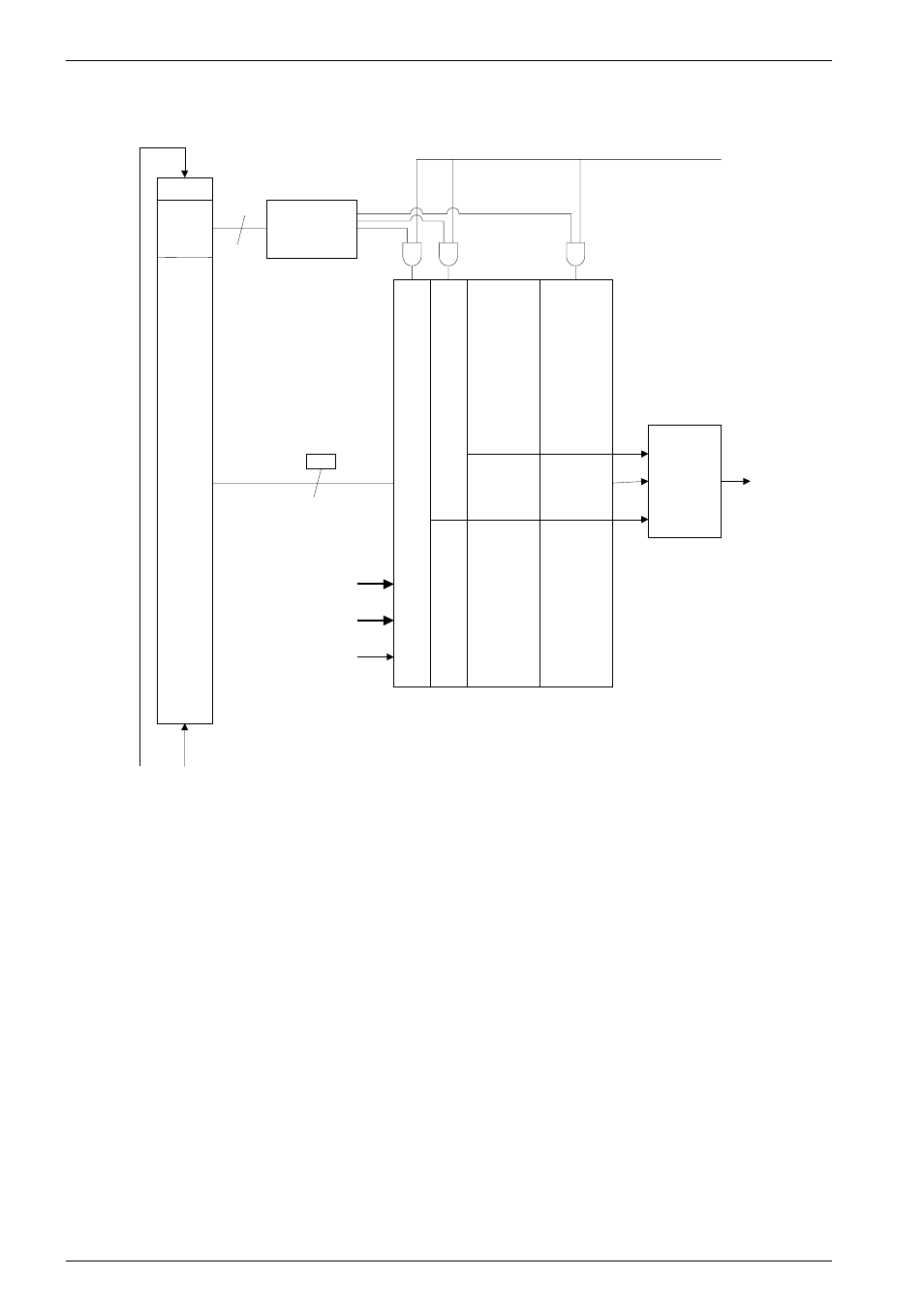
Figure 9-12 EmbeddedICE-RT block diagram
The data to be written is shifted into the 32-bit data field, the address of the register is shifted
into the 5-bit address field, and the read/write bit is set.
The data to be written is scanned into the 32-bit data field, the address of the register is
scanned into the 5-bit address field, and the read/write bit is set.
A register is read by shifting its address into the address field, and by shifting a 0 into the
read/write bit. The 32-bit data field is ignored.
The register addresses are shown in Table 9-1 on page 9-12.
Note:
A read or write takes place when the TAP controller enters the UPDATE-DR state.
read/write
0
4
31
0
Data
Scan chain
register
Address
Address decoder
DBGTDI DBGTDO
Value
Mask
Comparator
Control
DATA[31:0]
HADDR[31:0]
+
Breakpoint
condition
Watchpoint registers and comparators
Update
32