2 using the data, and address mask registers, 3 the watchpoint unit control registers, Figure 9-13 – Epson ARM.POWERED ARM720T User Manual
Page 167: Watchpoint control value, and mask format -35, Table 9-8, Size[1:0] signal encoding -35
9: Debugging Your System
ARM720T CORE CPU MANUAL
EPSON
9-35
9.20.2
Using the data, and address mask registers
For each value register in a register pair, there is a mask register of the same format. Setting
a bit to 1 in the mask register has the effect of making the corresponding bit in the value
register disregarded in the comparison.
For example, when a watchpoint is required on a particular memory location, but the data
value is irrelevant, the data mask register can be programmed to 0xffffffff (all bits set) to ignore
the entire data bus field.
Note:
The mask is an XNOR mask rather than a conventional AND mask. When a mask
bit is set to 1, the comparator for that bit position always matches, irrespective of
the value register or the input value.
Clearing the mask bit means that the comparator matches only if the input value matches the
value programmed into the value register.
9.20.3
The watchpoint unit control registers
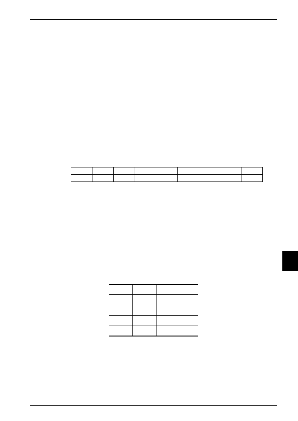
The control value and control mask registers are mapped identically in the lower eight bits, as
Figure 9-13 Watchpoint control value, and mask format
Bit 8 of the control value register is the ENABLE bit and cannot be masked.
The bits have the following functions:
WRITE
Compares against the write signal from the core in order to detect
the direction of bus activity. WRITE is 0 for a read cycle, and 1 for
a write cycle.
SIZE[1:0]
Compares against the HSIZE[1:0] signal from the core in order to
detect the size of bus activity.
The encoding is shown in Table 9-8.
PROT[0]
Is used to detect whether the current cycle is an instruction fetch
(PROT[0] = 0), or a data access (PROT[0] = 1).
PROT[1]
Is used to compare against the not translate signal from the core in
order to distinguish between user mode (PROT[1] = 0), and
non-User mode (PROT[1] = 1) accesses.
Table 9-8 SIZE[1:0] signal encoding
bit 1
bit 0
Data size
0
0
Byte
0
1
Halfword
1
0
Word
1
1
(Reserved)
ENABLE
CHAIN
RANGE
DBGEXT
PROT[0]
PROT[1]
SIZE[1]
WRITE
SIZE[0]
8
6
7
5
3
4
2
0
1