A.6 atpg test signals, A.7 miscellaneous signals, Table a-6 – Epson ARM.POWERED ARM720T User Manual
Page 207: Table a-7
A: Signal Descriptions
ARM720T CORE CPU MANUAL
EPSON
A-7
A.6
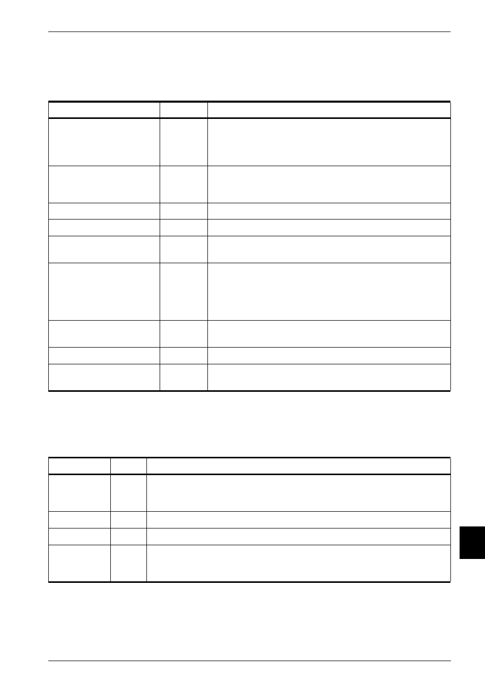
ATPG test signals
ATPG test signals used by the ARM720T processor are shown in Table A-6.
A.7
Miscellaneous signals
Miscellaneous signals used by the ARM720T processor are shown in Table A-7.
Table A-6 ATPG test signal descriptions
Name
Type
Description
TESTENABLE
Input
This signal ensures the clocks are free-running during scan
test. TESTENABLE must be:
•
tied HIGH throughout the duration of scan testing
•
tied LOW during functional mode.
SCANENABLE
Input
This signal enables serial shifting of vectors through the scan
chains. You must control this signal using the I/O pins. It must
be tied LOW during functional mode.
SCANIN0-SCANIN6
Inputs
Processor core scan chain inputs.
SCANOUT0-SCANOUT6
Outputs
Processor core scan chain outputs.
HCLK
Input
System clock. All signals are related to the rising edge of
HCLK.
HCLKEN
Input
Synchronous enable for AHB transfers. When HIGH,
indicates that the next rising edge of HCLK is also a rising
edge for the AHB system that the ARM720T processor is
embedded in. Must be tied HIGH in systems where the AMBA
bus and the core are intended to be the same frequency.
DBGTCKEN
Input
Synchronous enable for debug logic. Must be tied HIGH
during scan test.
HRESETn
Input
This is the active LOW reset signal for the system and bus.
DBGnTRST
Input
This is the active LOW reset signal for the internal state. This
signal is a level-sensitive asynchronous reset input.
Table A-7 Miscellaneous signal descriptions
Name
Type
Description
BIGENDOUT
Output Big-endian
format.
When this signal is HIGH, the processor treats bytes in memory as being in
big-endian format. When it is LOW, memory is treated as little-endian.
nFIQ
Input
ARM fast interrupt request signal.
nIRQ
Input
ARM interrupt request signal.
VINITHI
Input
Determines the state of the V bit in CP15 register c1 at reset. When HIGH, the
V bit is set coming out of rest. When LOW, the V bit is clear coming out of
reset.