1 addressing the cam, ram1, and ram2, Figure 11-16, Rd format, write tlb lockdown -12 – Epson ARM.POWERED ARM720T User Manual
Page 196: Table 11-10, Ram2 memory region size -12
11: Test Support
11-12
EPSON
ARM720T CORE CPU MANUAL
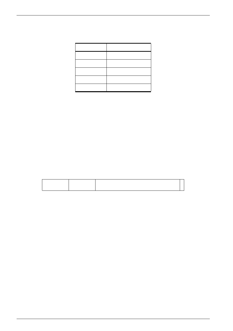
In Figure 11-15, SIZE_R2 sets the memory region size. The allowed values of SIZE_R2 are
Note:
The encoding for SIZE_R2 is different from SIZE_C.
11.5.1
Addressing the CAM, RAM1, and RAM2
For the CAM read or write, RAM1 read or write, and RAM2 read or write operations, you must
specify the index. The CAM and RAM1 operations use the value in the victim pointer, so you
must write this before any CAM or RAM1 operation. RAM2 uses a pipelined version of the
victim pointer used for the CAM or RAM1 operation. This means that to read from index N in
the RAM2 array, you must first perform an access to index N in either the CAM or RAM1.
The write TLB lockdown operation is:
MCR p15, 0,
The write TLB lockdown format for Rd is shown in Figure 11-16.
Figure 11-16 Rd format, write TLB lockdown
Table 11-10 RAM2 memory region size
SIZE_R2[3:0]
Memory region size
b1000
1MB
b0100
64KB
b0010
16KB
b0000
4KB
b0001
1KB
P
31
0
Base
SBZ
25
26
20 19
1
Victim