11 scan chains and the jtag interface, 1 scan chain implementation, Scan chain 1 – Epson ARM.POWERED ARM720T User Manual
Page 149: Scan chain 2, Scan chains and the jtag interface -17, Figure 9-7, Arm720t processor scan chain arrangements -17, Scan chains and, The jtag interface
9: Debugging Your System
ARM720T CORE CPU MANUAL
EPSON
9-17
9.11
Scan chains and the JTAG interface
There are three JTAG-style scan chains within the ARM720T processor. These enable
debugging and EmbeddedICE-RT programming.
A JTAG-style
Test Access Port
(TAP) controller controls the scan chains. For more details of
the JTAG specification, see IEEE Standard 1149.1 - 1990
Standard Test Access Port and
Boundary-Scan Architecture
.
9.11.1
Scan chain implementation
The three scan paths on the ARM720T processor are referred to as scan chain 1, scan chain 2,
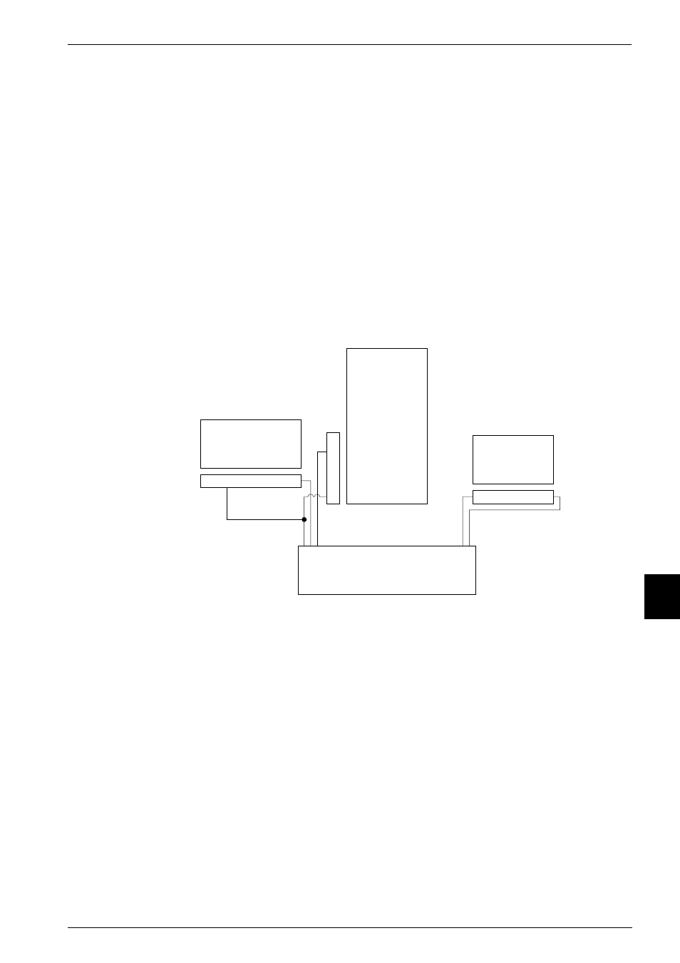
and scan chain 15. They are shown in Figure 9-7.
Debug scan chain 0 is not implemented in the ARM720T processor, but all the control signals
are provided at the macrocell boundary. This enables you to design your own boundary scan
chain wrapper if required.
Figure 9-7 ARM720T processor scan chain arrangements
Scan chain 1
Scan chain 1 provides serial access to the core data bus HRDATA/HWDATA and the
DBGBREAK signal.
There are 33 bits in this scan chain, the order being (from serial data in to out):
•
data bus bits 0 through 31
•
the DBGBREAK bit (the first to be shifted out).
Scan chain 2
Scan chain 2 enables access to the EmbeddedICE-RT registers. See
ARM720T
processor
System control
processor
ARM720T
EmbeddedICE-RT
Scan chain 2
Scan chain 15
ARM720T TAP controller
(also provides scan chain 0
control signals)
S
c
an
c
hain
1