Figure 9-17, Debug control and status register structure -42 – Epson ARM.POWERED ARM720T User Manual
Page 174
9: Debugging Your System
9-42
EPSON
ARM720T CORE CPU MANUAL
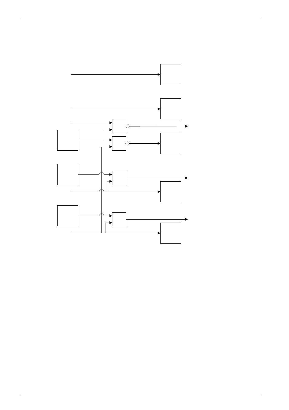
The structure of the debug control and status registers is shown in Figure 9-17.
Figure 9-17 Debug control and status register structure
Bit 4
Bit 3
Bit 2
Bit 1
Bit 0
Bit 0
Bit 2
Bit 1
Debug
control
register
Debug
status
register
TBIT
(from core)
TRANS[1]
(from core)
+
+
+
+
DBGACKI
(from core)
Interrupt mask enable
(to core)
DBGRQ
(from ARM720T input)
DBGACKI
(from core)
DBGACK
(to ARM720T processor
output)
DBGRQI
(to core)
See also other documents in the category Epson Hardware:
- C8230 (29 pages)
- 400 (38 pages)
- 400 (148 pages)
- 600 (135 pages)
- 640 (45 pages)
- 700 (10 pages)
- 850 (147 pages)
- 1520 (40 pages)
- C82314 (71 pages)
- RS-485 (2 pages)
- 6200A (97 pages)
- C82307 (37 pages)
- UB E02 (86 pages)
- 440 (240 pages)
- 440 (212 pages)
- 660 (92 pages)
- 5000 (154 pages)
- 5000 (176 pages)
- 9000 (68 pages)
- SD-DSPUSBB (2 pages)
- CMD-2260 (18 pages)
- C823301 (17 pages)
- S1C6200A (98 pages)
- 33+ (10 pages)
- FEH300b (46 pages)
- SED 1520 Series (40 pages)
- Serial Interface GQ-3500 (13 pages)
- ETX-945 (39 pages)
- Photo EX (35 pages)
- C82364 (279 pages)
- 214D-1 (57 pages)
- EM07ZS1647F (168 pages)
- Connect-It SD-DSWIFIB (2 pages)
- ACTIONPC 7000 (10 pages)
- S5U1C63000H2 (35 pages)
- C824 (4 pages)
- C82069* (46 pages)
- 80211b (68 pages)
- C82312 (13 pages)
- S5U1C17801T1100 (60 pages)
- C82324* (57 pages)
- C82372 (22 pages)
- C82315 (48 pages)
- P07303 (36 pages)