12 the tap controller, 1 resetting the tap controller, The tap controller -19 – Epson ARM.POWERED ARM720T User Manual
Page 151: Figure 9-8, Test access port controller state transitions -19, The tap controller
9: Debugging Your System
ARM720T CORE CPU MANUAL
EPSON
9-19
9.12
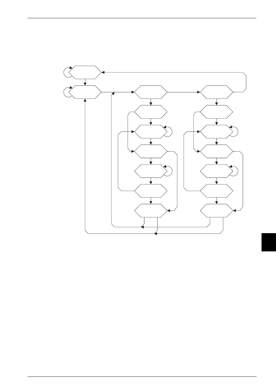
The TAP controller
The TAP controller is a state machine that determines the state of the boundary-scan test
signals DBGTDI and DBGTDO. Figure 9-8 shows the state transitions that occur in the TAP
controller.
Figure 9-8 Test access port controller state transitions
From IEEE Std 1149.1-1990. Copyright 2001 IEEE. All rights reserved.
9.12.1
Resetting the TAP controller
To force the TAP controller into the correct state after power-up, you must apply a reset pulse
to the DBGnTRST signal:
•
When the boundary-scan interface is to be used, DBGnTRST must be driven LOW
and then HIGH again.
•
When the boundary-scan interface is not to be used, you can tie the DBGnTRST
input LOW.
The action of reset is as follows:
1
System mode is selected. This means that the boundary-scan cells do not intercept
any of the signals passing between the external system and the core.
2
The IDCODE instruction is selected.
When the TAP controller is put into the SHIFT-DR state and HCLK is pulsed while
enabled by DBGTCKEN, the contents of the ID register are clocked out of
DBGTDO.
Test-Logic Reset
0xF
Run-Test/Idle
0xC
Select-DR-Scan
0x7
Capture-DR
0x6
Capture-IR
0xE
Shift-DR
0x2
Shift-IR
0xA
Exit1-DR
0x1
Exit1-IR
0x9
Pause-DR
0x3
Pause-IR
0xB
Exit2-DR
0x0
Exit2-IR
0x8
Update-DR
0x5
Update-IR
0xD
Select-IR-Scan
0x4
tms=1
tms=0
tms=0
tms=1
tms=1
tms=1
tms=0
tms=0
tms=1
tms=0
tms=1
tms=1
tms=1
tms=0
tms=0
tms=1
tms=1
tms=1
tms=0
tms=1
tms=0
tms=0
tms=1
tms=0
tms=1
tms=1
tms=0
tms=1
tms=0
tms=0
tms=0
tms=0