6 coordinate plane setting (pln), 1) overview, 2) format – Yaskawa MP2000 Series: User's Manual for Motion Programming User Manual
Page 193: 3) programming examples, 2) format (3) programming examples
8 Command Reference
8.3.6 Coordinate Plane Setting (PLN)
8-86
8.3.6 Coordinate Plane Setting (PLN)
(1) Overview
The Coordinate Plane Setting command (PLN) defines two logical axes set in the parameters to designate a coor-
dinate plane. Always execute a PLN command before executing a Circular Interpolation command (MCW,
MCC) and Helical Interpolation command (MCW, MCC).
The designated coordinate plane remains in effect until it is reset by another PLN command or until the END
command.
(2) Format
(3) Programming Examples
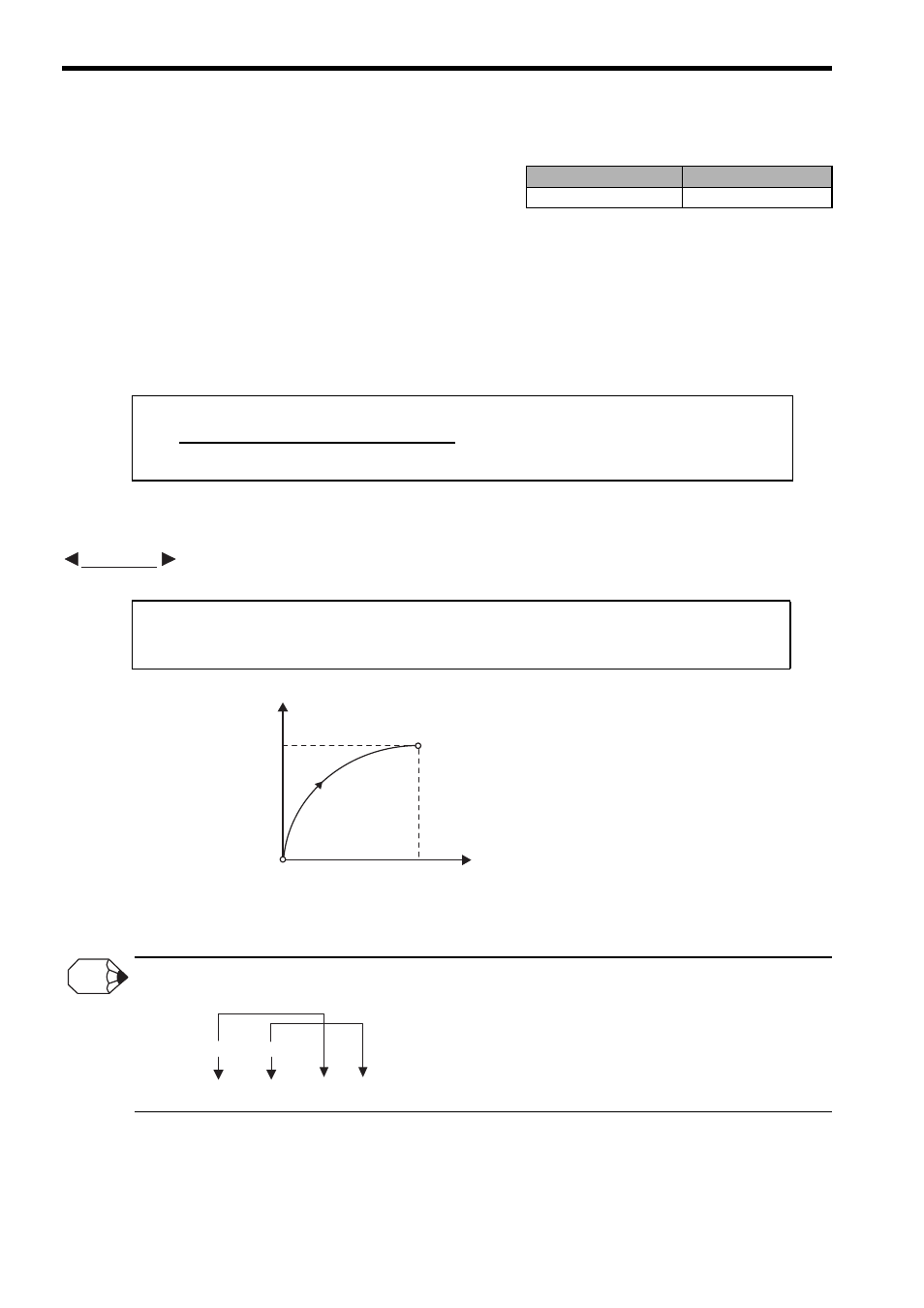
A PLN command programming example is shown below.
Fig. 8.52 PLN Command Programming Example
Designate an end position and a center position for circular interpolation and helical interpolation in the same order used to
specify the axes in the PLN command block.
Motion Programs
Sequence Programs
Applicable
Not applicable
Horizontal axis name Vertical axis name
PLN [Logical axis name 1] [Logical axis name 2] ;
Designate two axes of a coordinate plane.
PLN[A1][B1]; " Designates the plane composed of axes A1 and B1
MCW [A1]50 [B1]50 R50 F1000;
EXAMPLE
B1
50
50
(0,0)
A1
End position
Program
current position
INFO
PLN [
] [ ] ;
MCC [A1]1500 [B1]4000 U2500 V1000 F150;
Logical axis
name 1
Logical axis
name 2