T3: asr and inertia tuning – Yaskawa CIMR-AU 200V Drives User Manual
Page 333
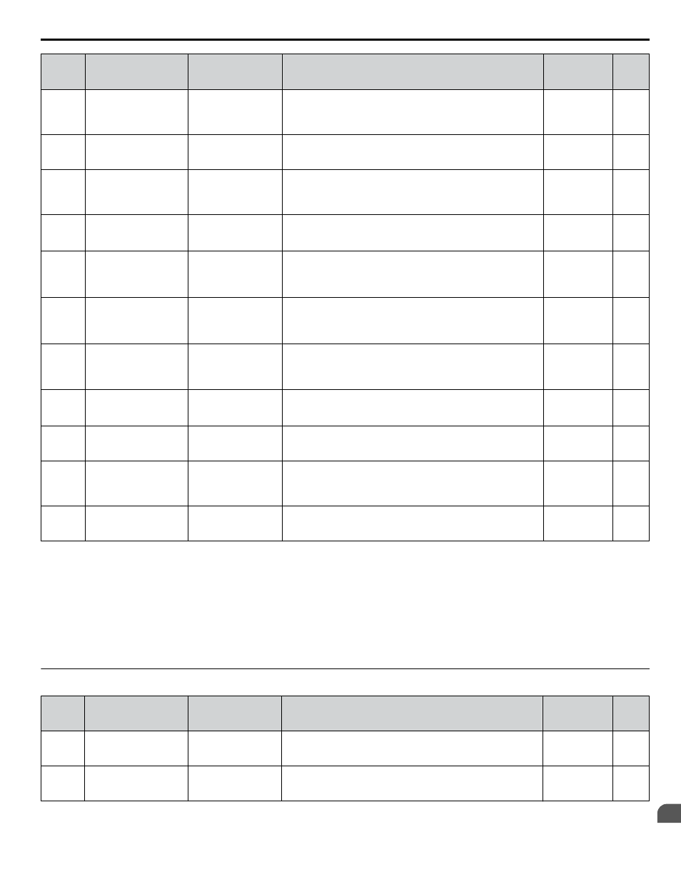
No.
(Addr.
Hex)
Name
LCD Display
Description
Values
Page
T2-07
(0753)
PM Motor Base
Frequency
Base Frequency
Enter the motor base frequency as indicated on the motor
nameplate.
Default: 87.5
Hz
Min.: 0.0
Max.: 400.0
–
T2-08
(0734)
Number of PM Motor
Poles
Number of Poles
Enter the number of motor poles for the PM motor as indicated
on the motor nameplate.
Default: 6
Min.: 2
Max.: 48
–
T2-09
(0731)
PM Motor Base Speed
Rated Speed
Enter the base speed for the PM motor as indicated on the motor
nameplate.
Default: 1750
r/min
Min.: 0
Max.: 24000
–
T2-10
(0754)
PM Motor Stator
Resistance
Arm Resistance
Enter the rotor resistance for the PM motor as indicated on the
motor nameplate.
Default:
<8>
Min.: 0.000 Ω
Max.: 65.000 Ω
–
T2-11
(0735)
PM Motor d-Axis
Inductance
d-Axis Induct
Enter the d-axis inductance for the PM motor as indicated on the
motor nameplate.
Default:
<8>
Min.: 0.00 mH
Max.: 600.00
mH
–
T2-12
(0736)
PM Motor q-Axis
Inductance
q-Axis Induct
Enter the q-axis inductance for the PM motor as indicated on the
motor nameplate.
Default:
<8>
Min.: 0.00 mH
Max.: 600.00
mH
–
T2-13
(0755)
Induced Voltage
Constant Unit Selection
Iduct Volt Unit
0: mV/RPM
1: mV/(rad/sec)
0: mV/(r/min). E5-09 will automatically be set to 0.0, and E5-24
will be used.
1: mV/(rad/sec). E5-24 will automatically be set to 0.0, and E5-09
will be used.
Default: 1
Range: 0, 1
–
T2-14
(0737)
PM Motor Induced
Voltage Constant
Induct Volt Coef
Enter the induced voltage coefficient for the PM motor as
indicated on the motor nameplate.
Default:
<8>
Min.: 0.0
Max.: 2000.0
–
T2-15
(0756)
Pull-In Current Level for
PM Motor Tuning
Pull-In I Lvl
Sets the amount of pull-in current to use for Auto-Tuning as a
percentage of the motor rated current. Increase this setting for
high inertia loads.
Default: 30%
Min.: 0
Max.: 120
–
T2-16
(0738)
PG Number of Pulses
Per Revolution for PM
Motor Tuning
PG Pulses/Rev
Sets the number of pulses per revolution for the PG being used
(pulse generator or encoder).
Default: 1024
ppr
Min.: 1
Max.: 15000
–
T2-17
(0757)
Encoder Z-Pulse Offset Z-Pulse Offset
Sets the offset between encoder offset and the rotor magnetic axis. Default: 0.0 deg
Min.: -180.0
Max.: 180.0
–
<1> The availability of certain Auto-Tuning methods is determined by the control mode selected for the drive.
<2> Available in drive software versions PRG: 1015 and later.
<3> Available in drive software versions PRG: 1018 and later.
<4> Available in drive software versions PRG: 1019 and later.
<5> Default setting is determined by parameters A1-02, Control Method Selection, and o2-04, Drive Model Selection.
<6> Default setting is determined by parameter o2-04, Drive Model Selection.
<7> Values shown are specific to 200 V class drives. Double the value for 400 V class drives. Multiply the value by 2.875 for 600 V class drives.
<8> Default setting is determined by parameter T2-02, PM Motor Code Selection, and the drive capacity.
u
T3: ASR and Inertia Tuning
No.
(Addr.
Hex)
Name
LCD Display
Description
Values
Page
T3-01
(0760) Test Signal Frequency
Test Signal Freq
Sets the frequency of the test signal used during Inertia Tuning
and ASR Gain Auto-Tuning. Reduce this value if the inertia is
large or if a fault occurs.
Default: 3.0 Hz
Min.: 0.1
Max.: 20.0
–
T3-02
(0761) Test Signal Amplitude
Test Signal Ampl
Sets the amplitude of the test signal used during Inertia and ASR
Gain Auto-Tuning. Reduce this value if the inertia is too large or
if a fault occurs.
Default: 0.5 rad
Min.: 0.1
Max.: 10.0
–
B.12 T: Motor Tuning
YASKAWA ELECTRIC TOEP C710616 41E YASKAWA AC Drive - A1000 Quick Start Guide
333
B
Parameter List