Yaskawa CIMR-AU 200V Drives User Manual
Page 185
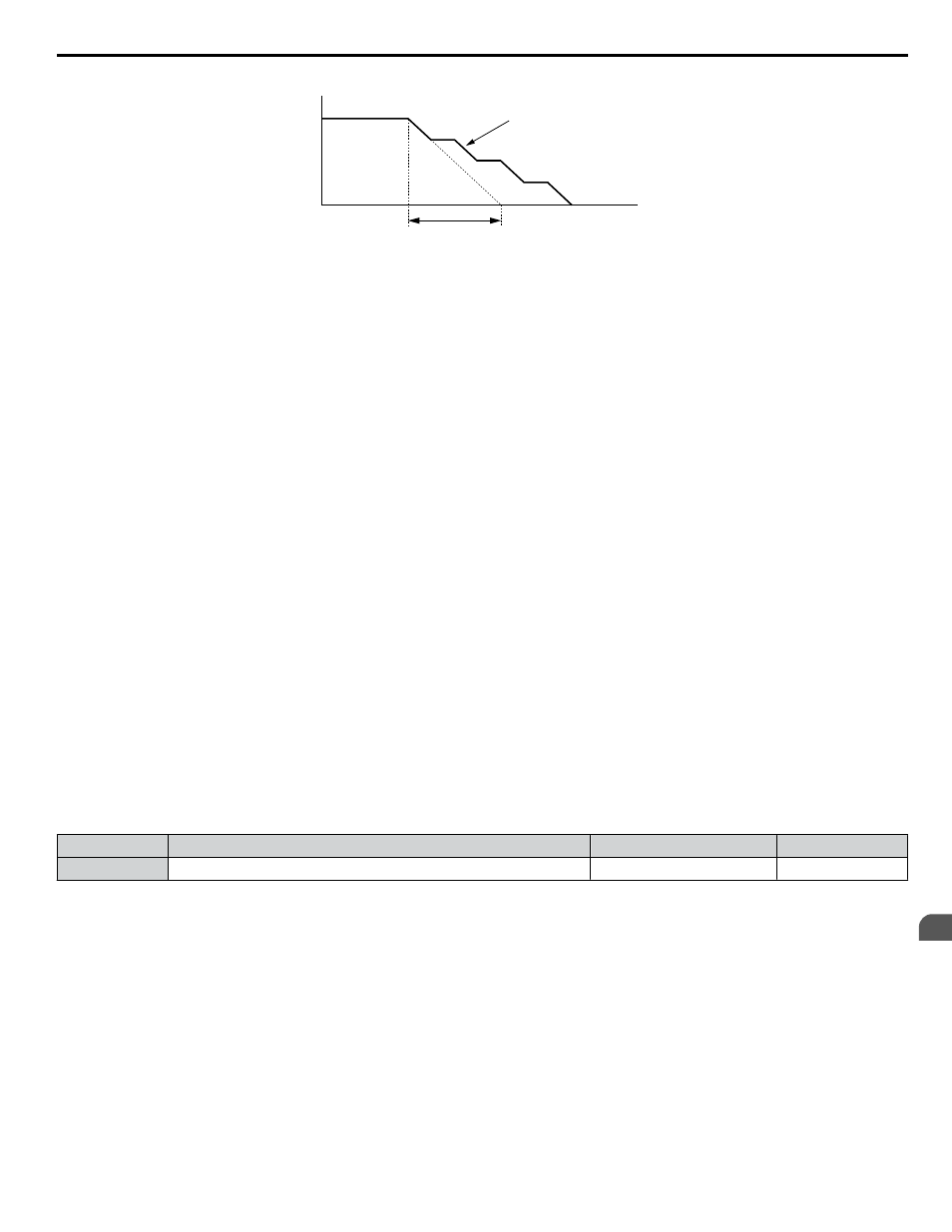
Output Frequency
Deceleration characteristics
when Stall Prevention was
triggered during deceleration
Time
specified deceleration time
Figure 4.36 Stall Prevention During Deceleration
Setting 2: Intelligent Stall Prevention
The drive adjusts the deceleration rate so the DC bus voltage is kept at the level set to parameter L3-17. This produces the
shortest possible deceleration time while protecting the motor from stalling. The selected deceleration time is disregarded and
the achievable deceleration time cannot be smaller than 1/10 of the set deceleration time.
This function uses the following parameters for adjusting the deceleration rate:
• DC bus voltage gain (L3-20)
• Deceleration rate calculations gain (L3-21)
• Inertia calculations for motor acceleration time (L3-24)
• Load inertia ratio (L3-25)
Note:
The deceleration time is not constant. Do not use Intelligent Stall Prevention in applications where stopping accuracy is a concern. Use
dynamic braking options instead.
Setting 3: Stall Prevention with Dynamic Braking Option
Enables the Stall Prevention function while using a dynamic braking resistor. Overvoltage problems in the DC bus can occur
if Stall Prevention during deceleration is disabled (L3-04) in OLV and a dynamic braking option is installed. Set L3-04 to 3
to remedy this situation.
Setting 4: Overexcitation Deceleration 1
Overexcitation Deceleration 1 (increasing the motor flux) is faster than deceleration with no Stall Prevention (L3-04 = 0).
Setting 4 changes the selected decel time and functions to provide protection from an overvoltage trip.
Setting 5: Overexcitation Deceleration 2
Overexcitation Deceleration 2 slows down the motor while trying to maintain the DC bus voltage at the level set to parameter
L3-17. This function shortens the achievable deceleration time more than by using Overexcitation Deceleration 1. Setting 5
will shorten/lengthen the decel time to maintain the L3-17 bus level.
n
L3-05: Stall Prevention Selection during Run
Determines how Stall Prevention works during Run. Stall Prevention during run prevents the motor from stalling by
automatically reducing the speed when a transient overload occurs while the motor is running at constant speed.
No.
Name
Setting Range
Default
L3-05
Stall Prevention Selection During Run
0 to 2
1
Note:
1. This parameter is available in V/f, V/f w/PG, and OLV/PM.
2. Stall Prevention during run is disabled when the output frequency is 6 Hz or lower regardless of the L3-05 and L3-06 settings.
Setting 0: Disabled
Drive runs at the set frequency reference. A heavy load may cause the motor to stall and trip the drive with an oC or oL fault.
Setting 1: Decelerate Using C1-02
If the current exceeds the Stall Prevention level set in parameter L3-06, the drive will decelerate at decel time 1 (C1-02). When
the current level drops below the value of L3-06 minus 2% for 100 ms, the drive accelerates back to the frequency reference
at the active acceleration time.
Setting 2: Decelerate Using C1-04
Same as setting 1 except the drive decelerates at decel time 2 (C1-04).
4.6 Basic Drive Setup Adjustments
YASKAWA ELECTRIC TOEP C710616 41E YASKAWA AC Drive - A1000 Quick Start Guide
185
4
Start-Up Programming & Operation