6 basic drive setup adjustments – Yaskawa CIMR-AU 200V Drives User Manual
Page 163
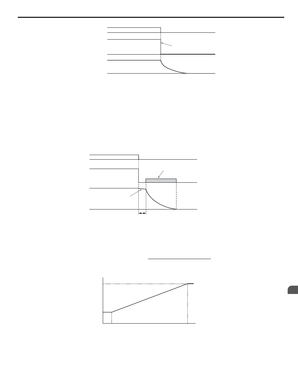
Drive output is shut off
Run
command
Output
frequency
Motor speed
ON
OFF
Figure 4.13 Coast to Stop
Note:
After a stop is initiated, any subsequent Run command entered will be ignored until the minimum baseblock time (L2-03) has expired. Do
not enter Run command until it has come to a complete stop. Use DC Injection at Start (
Refer to b2: DC Injection Braking and Short
) or Speed Search (
Refer to b3: Speed Search on page 268
) to restart the motor before it has completely
stopped.
Setting 2: DC Injection Braking to Stop
When the Run command is removed, the drive will enter baseblock (turn off its output) for the minimum baseblock time
(L2-03). When the minimum baseblock time has expired, the drive will inject the amount DC Injection Braking is set in
parameter b2-02 into the motor windings to brake the motor. The stopping time in DC Injection Braking to Stop is significantly
faster compared to Coast to Stop.
Note:
This function is not available in CLV or in control modes for PM motors (A1-02 = 5, 6, 7).
Motor coasts
DC Injection Braking
with the current set in
b2-02
Run
command
Output
frequency
ON
OFF
Motor speed
Minimum Baseblock
Time (L2-03)
Figure 4.14 DC Injection Braking to Stop
DC Injection Braking time is determined by the value set to b2-04 and the output frequency at the time the Run command is
removed. It can be calculated by:
DC Injection brake time
(b2-04) x 10 x Output frequency
Max. output frequency (E1-04)
=
Output frequency when
Stop command was entered
100%
(Maximum output
frequency)
10%
DC Injection braking time
b2-04×10
b2-04
Figure 4.15 DC Injection Braking Time Depending on Output Frequency
Note:
If an overcurrent (oC) fault occurs during DC Injection Braking to Stop, lengthen the minimum baseblock time (L2-03) until the fault no
longer occurs.
4.6 Basic Drive Setup Adjustments
YASKAWA ELECTRIC TOEP C710616 41E YASKAWA AC Drive - A1000 Quick Start Guide
163
4
Start-Up Programming & Operation