L3: stall prevention – Yaskawa CIMR-AU 200V Drives User Manual
Page 315
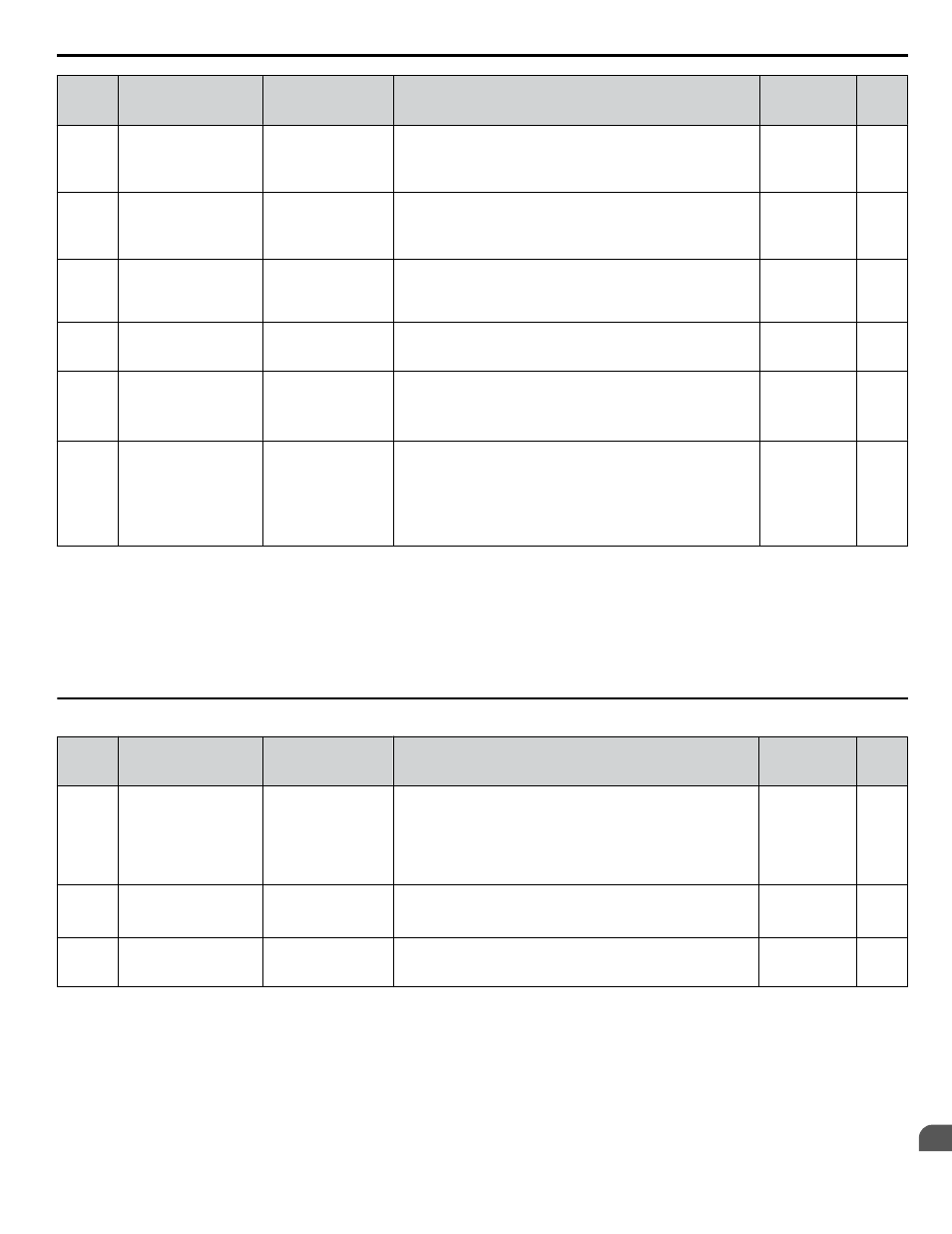
No.
(Addr.
Hex)
Name
LCD Display
Description
Values
Page
L2-06
(048A)
KEB Deceleration
Time
KEB Decel Time
Sets the time required to decelerate from the speed when KEB
was activated to zero speed.
Default: 0.00 s
Min.: 0.00
Max.: 6000.0
<4>
–
L2-07
(048B)
KEB Acceleration
Time
KEB Accel Time
Sets the time to accelerate to the frequency reference when
momentary power loss is over. If set to 0.0, the active acceleration
time (C1-01, C1-03, C1-05, or C1-07) is used.
Default: 0.00 s
Min.: 0.00
Max.: 6000.0
<4>
–
L2-08
(048C)
Frequency Gain at KEB
Start
KEB Freq Red
Sets the percentage of output frequency reduction at the
beginning of deceleration when the KEB Ride-Thru function is
started.
Reduction = (slip frequency before KEB) × (L2-08/100) × 2
Default: 100%
Min.: 0
Max.: 300
–
L2-10
(048E)
KEB Detection Time
(Minimum KEB Time) KEB Detect Time
Sets the time to perform KEB Ride-Thru.
Default: 50 ms
Min.: 0
Max.: 2000
–
L2-11
(0461)
DC Bus Voltage
Setpoint during KEB
KEB DC Bus Level
Sets the desired value of the DC bus voltage during KEB Ride-
Thru.
Default:
<2>
Min.: 150 Vdc
Max.: 400 Vdc
<5>
–
L2-29
(0475) KEB Method Selection
KEB Mode Sel
0: Single Mode KEB1
1: Single Mode KEB2
2: System Mode
KEB1
3: System Mode
KEB2
0: Single Drive KEB Ride-Thru 1
1: Single Drive KEB Ride-Thru 2
2: System KEB Ride-Thru 1
3: System KEB Ride-Thru 2
Default: 0
Range: 0 to 3
–
<1> Default setting is determined by parameters C6-01, Drive Duty Selection, and o2-04, Drive Model Selection.
<2> Default setting is determined by parameter E1-01, Input voltage Setting.
<3> Values shown are specific to 200 V class drives. Double the value for 400 V class drives. Multiply the value by 2.875 for 600 V class drives.
<4> Setting range value is dependent on parameter C1-10, Accel/Decel Time Setting Units. When C1-10 = 0 (units of 0.01 seconds), the setting range
becomes 0.00 to 600.00 seconds.
<5> Values shown are specific to 200 V class drives. Double the value for 400 V class drives. Multiply the value by 2.875 for 600 V class drives, but
set the value below 1040 Vdc (overvoltage protection level).
u
L3: Stall Prevention
No.
(Addr.
Hex)
Name
LCD Display
Description
Values
Page
L3-01
(048F)
Stall Prevention
Selection during
Acceleration
StallP Accel Sel
0: Disabled
1: General Purpose
2: Intelligent
0: Disabled.
1: General purpose. Acceleration is paused as long as the current
is above the L3-02 setting.
2: Intelligent. Accelerate in the shortest possible time without
exceeding the L3-02 level.
Note:
Setting 2 is not available when using OLV/PM.
Default: 1
Range: 0 to 2
L3-02
(0490)
Stall Prevention Level
during Acceleration
StallP Accel Lvl
Used when L3-01 = 1 or 2. 100% is equal to the drive rated
current.
Default:
<1>
Min.: 0%
Max.: 150%
<1>
L3-03
(0491)
Stall Prevention Limit
during Acceleration
StallPAcc LowLim
Sets Stall Prevention lower limit during acceleration when
operating in the constant power range. Set as a percentage of drive
rated current.
Default: 50%
Min.: 0
Max.: 100
B.8 L: Protection Function
YASKAWA ELECTRIC TOEP C710616 41E YASKAWA AC Drive - A1000 Quick Start Guide
315
B
Parameter List