Yaskawa CIMR-AU 200V Drives User Manual
Page 206
Values set to parameters L8-93, L8-94, and
L8-95 are incorrect.
• Increase the value set to L8-93.
• Increase the value set to L8-94.
• Increase the value set to L8-95.
<1> This function prevents continuous operation in reverse when using high frequency injection (n8-57 = 1) in AOLV/PM (A1-02 = 6) with a motor
for which no motor code has been entered (it does not only prevent reverse operation). Set L8-93, L8-94, and L8-95 to low values within range of
erroneous detection to quickly detect undesirable reverse operation.
Digital Operator Display
Fault Name
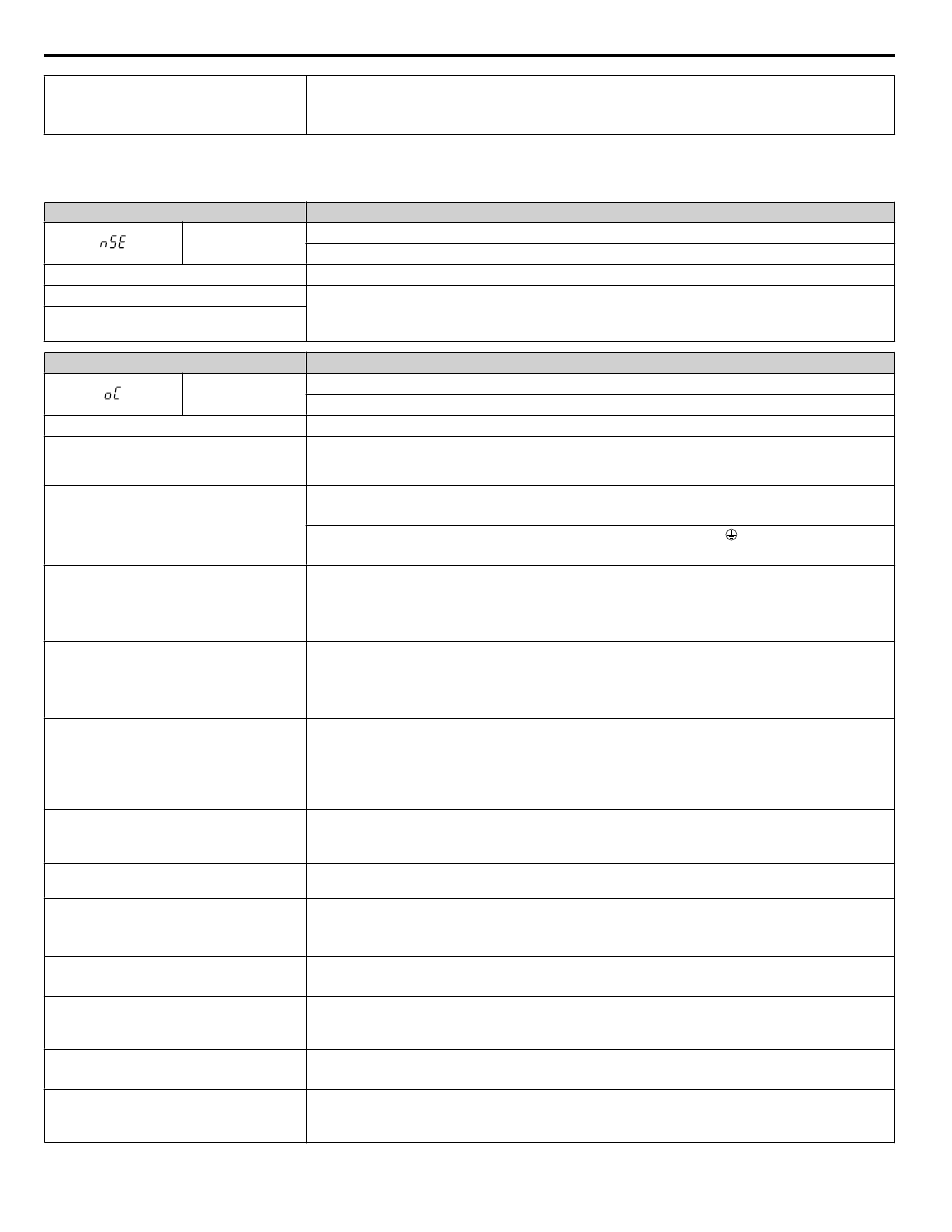
nSE
Node Setup Error
A terminal assigned to the node setup function closed during run.
Cause
Possible Solution
The node setup terminal closed during run.
Stop the drive when using the node setup function.
A Run command was issued while the node
setup function was active.
Digital Operator Display
Fault Name
oC
Overcurrent
Drive sensors detected an output current greater than the specified overcurrent level.
Cause
Possible Solution
The motor has been damaged due to
overheating or the motor insulation is
damaged
• Check the insulation resistance.
• Replace the motor.
One of the motor cables has shorted out or
there is a grounding problem
• Check the motor cables.
• Remove the short circuit and reapply power to the drive.
• Check the resistance between the motor cables and the ground terminal .
• Replace damaged cables.
The drive is damaged
• Check the drive output side short circuit for a broken output transistor
B1 and U/T1, V/T2, W/T3
– and U/T1, V/T2, W/T3
• Contact your Yaskawa representative or nearest Yaskawa sales office.
The load is too heavy
• Measure the current flowing into the motor.
• Replace the drive with a larger capacity drive if the current value exceeds the rated current.
• Determine if there is sudden fluctuation in the current level.
• Reduce the load to avoid sudden changes in the current level or switch to a larger drive.
The acceleration or deceleration times are too
short
Calculate the torque needed during acceleration relative to the load inertia and the specified acceleration
time. If it is not possible to set the proper amount of torque, make the following changes:
• Increase the acceleration time (C1-01, C1-03, C1-05, C1-07)
• Increase the S-curve characteristics (C2-01 through C2-04)
• Increase the capacity of the drive.
The drive is attempting to operate a specialized
motor or a motor larger than the maximum size
allowed
• Check the motor capacity.
• Ensure that the rated capacity of the drive is greater than or equal to the capacity rating found on the
motor nameplate.
Magnetic contactor (MC) on the output side of
the drive has turned on or off
Set up the operation sequence so the MC does not trip while the drive is outputting current.
V/f setting is not operating as expected
• Check the ratios between the voltage and frequency.
• Set parameters E1-04 through E1-10 appropriately (E3-04 through E3-10 for motor 2).
• Lower the voltage if it is too high relative to the frequency.
Excessive torque compensation
• Check the amount of torque compensation.
• Reduce the torque compensation gain (C4-01) until there is no speed loss and less current.
Drive fails to operate properly due to electrical
signal interference
• Review the possible solutions provided for handling electrical signal interference.
• Review the section on handling noise interference and check the control circuit lines, main circuit lines,
and ground wiring.
Overexcitation gain is set too high
• Check if the fault occurs simultaneously with overexcitation function operation.
• Consider motor flux saturation and reduce the value of n3-13 (Overexcitation Deceleration Gain).
Run command was applied while motor was
coasting
• Set b3-01 to 1 to enable Speed Search at Start.
• Program the Speed Search command input through one of the multi-function contact input terminals
(H1-oo = 61 or 62).
5.2 Fault Detection
206
YASKAWA ELECTRIC TOEP C710616 41E YASKAWA AC Drive - A1000 Quick Start Guide