1 option card installation, Prior to installing the option – Yaskawa CIMR-AU 200V Drives User Manual
Page 236
7.1 Option Card Installation
This section provides instructions on installing option cards.
u
Prior to Installing the Option
Prior to installing the option, wire the drive, make necessary connections to the drive terminals, and verify that the drive
functions normally without the option installed.
below lists the number of options that can be connected to the drive and the drive ports for connecting those options.
Table 7.1 Option Installation
Option
Port/Connector
Number of Options Possible
PG-B3, PG-X3
CN5-C
2
<1>
PG-F3
<2> <3>
, PG-RT3
<2> <3>
CN5-C
1
AO-A3, DO-A3
CN5-A, B, C
1
SI-B3
<3>
, SI-C3, SI-EN3
<3>
, SI-EM3
<3>
, SI-EP3
<3>
, SI-ES3
<3>
,
SI-ET3
<3>
, SI-N3, SI-P3, SI-S3, SI-T3, SI-W3
<3>
, AI-A3
<4>
, DI-A3
<4>
CN5-A
1
<1> When connecting two PG option cards, use both CN5-B and CN5-C. When connecting only one PG option card, use the CN5-C connector.
<2> Not available for the application with Motor 2 Selection.
<3> Not available with models 4A0930 and 4A1200.
<4> When using AI-A3 and DI-A3 as monitors, the card can be connected to any of CN5-A, CN5-B or CN5-C. The input status of AI-A3 can then be
viewed using U1-21, U1-22, and U1-23, and the input status of DI-A3 can then be viewed using U1-17.
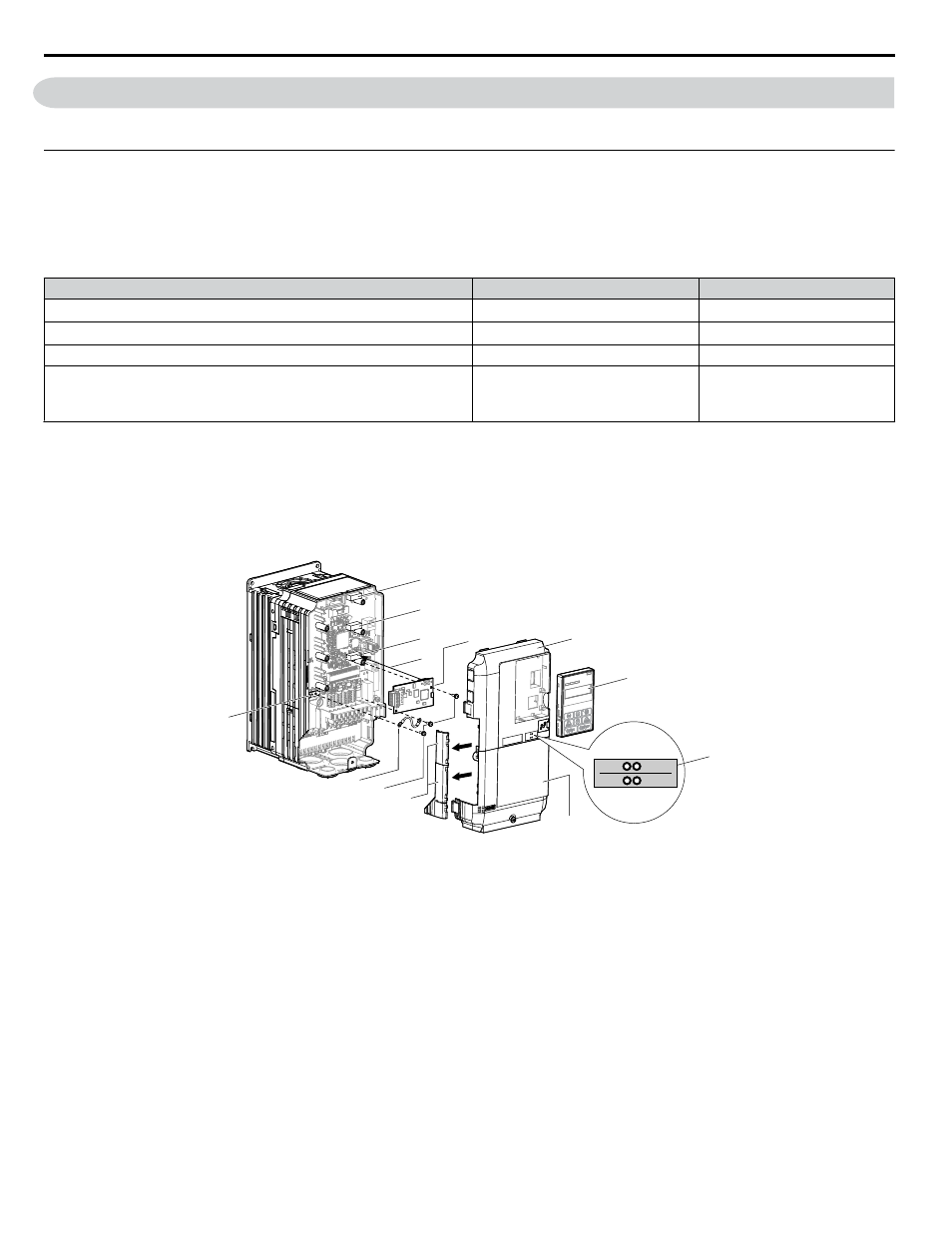
shows an exploded view of the drive with the option and related components for reference.
I
J
K
M
A
L
D
F
G
C
E
B
H
NS
MS
NS
MS
TX
RX
A – Drive front cover
B – Digital operator
C – LED label (for communication
options)
D – Drive terminal cover
E – Removable tabs for wire routing
F – Included screws
G – Ground wire
H – Drive grounding terminal (FE)
I – Connector CN5-C
J – Connector CN5-B
K – Connector CN5-A
L – Insertion point for CN5 connector
M – Option
Figure 7.1 Drive Components with Option
7.1 Option Card Installation
236
YASKAWA ELECTRIC TOEP C710616 41E YASKAWA AC Drive - A1000 Quick Start Guide