Pg option installation example – Yaskawa CIMR-AU 200V Drives User Manual
Page 237
u
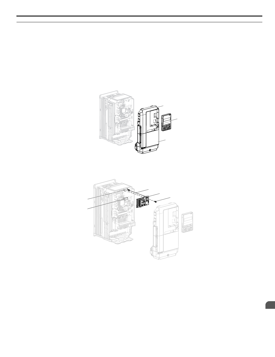
PG Option Installation Example
Remove the front covers of the drive before installing the option. PG options can inserted into the CN5-B or CN5-C connectors
located on the drive control board.
1.
Shut off power to the drive, wait the appropriate amount of time for voltage to dissipate, then remove the digital operator
(B) and front covers (A, D). Front cover removal varies by model.
DANGER! Electrical Shock Hazard. Do not connect or disconnect wiring while the power is on. Failure to comply will result in death
or serious injury. Before installing the option, disconnect all power to the drive. The internal capacitor remains charged even after
the power supply is turned off. The charge indicator LED will extinguish when the DC bus voltage is below 50 Vdc. To prevent
electric shock, wait at least five minutes after all indicators are off and measure the DC bus voltage level to confirm safe level.
NOTICE: Damage to Equipment. Observe proper electrostatic discharge procedures (ESD) when handling the option, drive, and
circuit boards. Failure to comply may result in ESD damage to circuitry.
A
B
D
Figure 7.2 Remove the Front Covers and Digital Operator
2.
Insert the option (M) into the CN5-B or CN5-C connector (I, J) located on the drive and fasten it using one of the
included screws (F). When connecting only one PG option, use the CN5-C connector.
J
I
M
F
L
Figure 7.3 Insert the Option
3.
Connect the ground wire (G) to the ground terminal (H) using one of the remaining provided screws (F). Connect the
other end of the ground wire (G) to the remaining ground terminal and installation hole on the option (M) using the
last remaining provided screw (F) and tighten both screws to 0.5 ~ 0.6 N m or (4.4 ~ 5.3 in lbs).
7.1 Option Card Installation
YASKAWA ELECTRIC TOEP C710616 41E YASKAWA AC Drive - A1000 Quick Start Guide
237
7
Peripheral Devices & Options