6 basic drive setup adjustments – Yaskawa CIMR-AU 200V Drives User Manual
Page 174
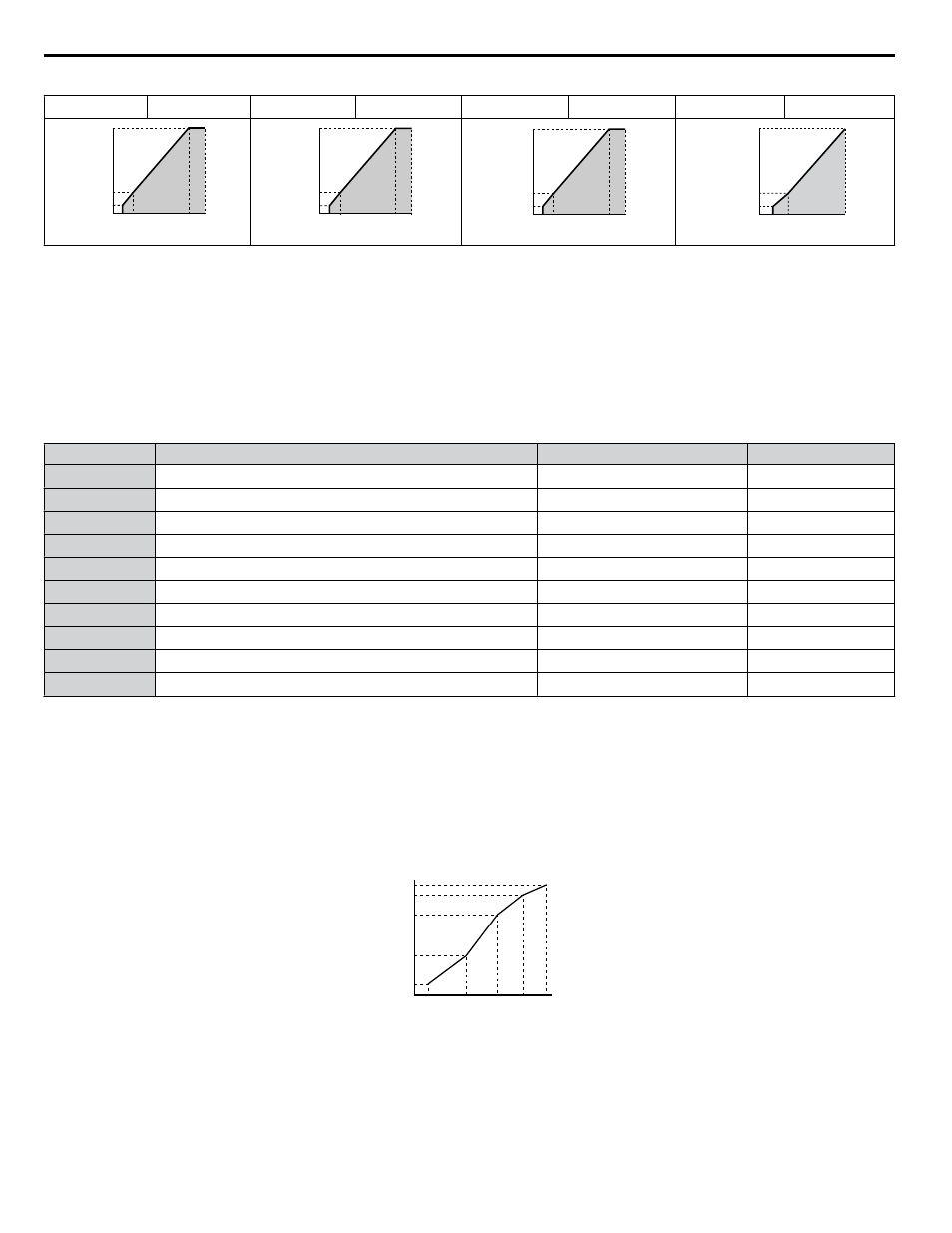
Table 4.25 Constant Output, Settings C to F
Setting = C
90 Hz
Setting = D
120 Hz
Setting = E
180 Hz
Setting = F
60 Hz
0
6
12
200
1.5 3
90
60
V
oltage (V)
Frequency (Hz)
0
6
12
200
1.5 3
120
60
V
oltage (V)
Frequency (Hz)
0
6
12
200
1.5 3
180
60
V
oltage (V)
Frequency (Hz)
0
6.9
230
1.5 3
60
13.8
V
oltage (V)
Frequency (Hz)
Setting a Custom V/f Pattern (Setting F: Default)
Setting parameter E1-03 to F allows the user to set up a custom V/f pattern by changing parameters E1-04 to E1-13.
When initialized, the default values for parameters E1-04 to E1-13 will be equal to Predefined V/f pattern 1.
n
V/f Pattern Settings E1-04 to E1-13
If E1-03 is set to a preset V/f pattern (i.e., a value other than F), the user can monitor the V/f pattern in parameters E1-04
through E1-13. To create a new V/f pattern, set E1-03 to F.
Refer to V/f Pattern on page 174
pattern.
Note:
Certain E1-oo parameters might not be visible depending on the control mode.
Refer to Parameter List on page 263
No.
Parameter Name
Setting Range
Default
E1-04
Maximum Output Frequency
40.0 to 400.0 Hz
<1>
<2> <3>
E1-05
Maximum Voltage
0.0 to 255.0 V
<4>
<2>
E1-06
Base Frequency
0.0 to [E1-04]
<2> <3>
E1-07
Middle Output Frequency
0.0 to [E1-04]
<2>
E1-08
Middle Output Frequency Voltage
0.0 to 255.0 V
<4>
<2>
E1-09
Minimum Output Frequency
0.0 to [E1-04]
<1>
<2> <3>
E1-10
Minimum Output Frequency Voltage
0.0 to 255.0 V
<4>
<2>
E1-11
Middle Output Frequency 2
0.0 to [E1-04]
0.0 Hz
<6>
E1-12
Middle Output Frequency Voltage 2
0.0 to 255.0 V
<4>
0.0 V
<5>
<6>
E1-13
Base Voltage
0.0 to 255.0 V
<4>
0.0 V
<5>
<7>
<1> Default setting is determined by E5-01 in OLV/PM. When E5-01 is set to FFFFH, the setting range for E1-04 and E1-06 is 10.0 to 40.0 Hz and the
setting range for E1-09 is 0.0 to 400.0 Hz.
<2> Default setting is determined by the control mode.
<3> When using PM motors, the default setting is determined by the motor code set to E5-01.
<4> Values shown are specific to 200 V class drives. Double the value for 400 V class drives. Multiply the value by 2.875 for 600 V class drives.
<5> The drive changes these settings when Auto-Tuning is performed (Rotational Auto-Tuning, Stationary Auto-Tuning 1, 2).
<6> Parameter ignored when E1-11 and E1-12 are set to 0.0.
<7> E1-13 and E1-05 are set to the same value when Auto-Tuning is performed.
Output Voltage (V)
Frequency (Hz)
E1-05
E1-12
E1-13
E1-08
E1-10
E1-09
E1-07 E1-06 E1-11 E1-04
Figure 4.24 V/f Pattern
Note:
1. The following condition must be true when setting up the V/f pattern: E1-09 ≤ E1-07 < E1-06 ≤ E1-11 ≤ E1-04
2. To make the V/f pattern a straight line below E1-06, set E1-09 equal to E1-07. In this case the E1-08 setting is disregarded.
3. E1-03 is unaffected when the drive is initialized, but E1-04 through E1-13 return to their default values.
4. Only use E1-11, E1-12, and E1-13 to fine-tune the V/f pattern in the constant output range. These parameters rarely need to be changed.
4.6 Basic Drive Setup Adjustments
174
YASKAWA ELECTRIC TOEP C710616 41E YASKAWA AC Drive - A1000 Quick Start Guide