Yaskawa CIMR-AU 200V Drives User Manual
Page 212
The braking transistor is damaged
• Cycle power to the drive and check for reoccurrence of the fault.
• Replace either the control board or the entire drive. For instructions on replacing the control board,
contact Yaskawa or a Yaskawa representative.
The control circuit is damaged
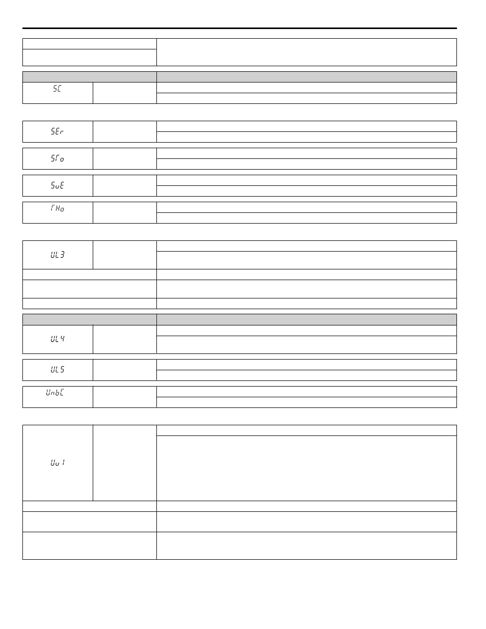
Digital Operator Display
Fault Name
<1>
SC
Output Short Circuit or IGBT Fault
Short circuit or ground fault is detected.
<1> Available in drive software versions PRG: 1015 and later.
SEr
Too Many Speed Search Restarts
The number of Speed Search restarts exceeded the value set to b3-19.
STo
Pull-Out Detection
Motor pull out or step out has occurred. Motor has exceeded its pull-out torque.
SvE
Zero Servo Fault
Position deviation during zero servo.
<1>
THo
Thermistor Disconnect
The thermistor that detects motor temperature has become disconnected.
<1> Detected in models 4A0930 and 4A1200.
UL3
Undertorque Detection 1
The current has fallen below the minimum value set for torque detection (L6-02) for longer than the
allowable time (L6-03).
Cause
Possible Solution
Parameter settings are not appropriate for the
load
Check the settings of parameters L6-02 and L6-03.
There is a fault on the machine side
Check the load for any problems.
Digital Operator Display
Fault Name
UL4
Undertorque Detection 2
The current has fallen below the minimum value set for torque detection (L6-05) for longer than the
allowable time (L6-06).
UL5
Mechanical Weakening Detection 2
The operation conditions matched the conditions set to L6-08.
<1>
UnbC
Current Unbalance
Current flow has become unbalanced.
<1> Detected in models 4A0930 and 4A1200.
Uv1
DC Bus Undervoltage
One of the following conditions occurred while the drive was running:
• Voltage in the DC bus fell below the undervoltage detection level (L2-05).
• For 200 V class drives: approximately 190 V
• For 400 V class drives: approximately 380 V (350 V when E1-01 is less than 400)
• For 600 V class drives: approximately 475 V
The fault is output only if L2-01 is set to 0 or 1 and the DC bus voltage has fallen below the level set to
L2-05 for longer than the time set to L2-02.
Cause
Possible Solution
Input power phase loss
• The main circuit drive input power is wired incorrectly.
• Correct the wiring.
One of the drive input power wiring terminals
is loose
• Ensure there are no loose terminals.
• Apply the tightening torque specified in this manual to fasten the terminals.
Wire Gauges and Tightening Torque on page 120
5.2 Fault Detection
212
YASKAWA ELECTRIC TOEP C710616 41E YASKAWA AC Drive - A1000 Quick Start Guide