B.9 n: special adjustment, N1: hunting prevention, N2: speed feedback detection control (afr) tuning – Yaskawa CIMR-AU 200V Drives User Manual
Page 323
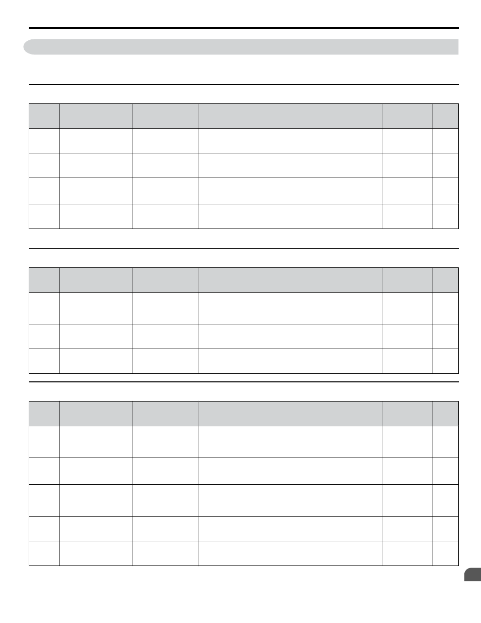
B.9 n: Special Adjustment
The n parameters adjust more advanced performance characteristics such as Hunting Prevention, speed feedback detection,
High Slip Braking, and Online Tuning for motor line-to-line resistance.
u
n1: Hunting Prevention
No.
(Addr.
Hex)
Name
LCD Display
Description
Values
Page
n1-01
(0580)
Hunting Prevention
Selection
Hunt Prev Select
0: Disabled
1: Enabled
0: Disabled
1: Enabled
Default: 1
Range: 0, 1
–
n1-02
(0581)
Hunting Prevention
Gain Setting
Hunt Prev Gain
If the motor vibrates while lightly loaded, increase the gain by
0.1 until vibration ceases. If the motor stalls, decrease the gain
by 0.1 until the stalling ceases.
Default: 1.00
Min.: 0.00
Max.: 2.50
–
n1-03
(0582)
Hunting Prevention
Time Constant
Hunt Prev Time
Sets the time constant used for Hunting Prevention.
Default:
<1>
Min.: 0 ms
Max.: 500 ms
–
n1-05
(0530)
Hunting Prevention
Gain while in Reverse
Hprev Gain @Rev
Sets the gain used for Hunting Prevention. If set to 0, the gain set
to n1-02 is used for operation in reverse.
Default: 0.00
Min.: 0.00
Max.: 2.50
–
<1> Default setting is determined by parameter o2-04, Drive Model Selection.
u
n2: Speed Feedback Detection Control (AFR) Tuning
No.
(Addr.
Hex)
Name
LCD Display
Description
Values
Page
n2-01
(0584)
Speed Feedback
Detection Control
(AFR) Gain
AFR Gain
Sets the internal speed feedback detection control gain in the
automatic frequency regulator (AFR).
If hunting occurs, increase the set value. If response is low,
decrease the set value.
Default: 1.00
Min.: 0.00
Max.: 10.00
–
n2-02
(0585)
Speed Feedback
Detection Control
(AFR) Time Constant 1
AFR Time
Sets the time constant used for speed feedback detection control
(AFR).
Default: 50 ms
Min.: 0
Max.: 2000
–
n2-03
(0586)
Speed Feedback
Detection Control
(AFR) Time Constant 2
AFR Time 2
Sets the AFR time constant to be used during Speed Search and
during regen.
Default: 750 ms
Min.: 0
Max.: 2000
–
u
n3: High Slip Braking (HSB) and Overexcitation Braking
No.
(Addr.
Hex)
Name
LCD Display
Description
Values
Page
n3-01
(0588)
High-Slip Braking
Deceleration Frequency
Width
HSB DecStepWidth
Sets the output frequency reduction step width for when the drive
stops the motor using HSB. Set as a percentage of the maximum
output frequency. Increase this setting if overvoltage occurs
during HSB.
Default: 5%
Min.: 1
Max.: 20
–
n3-02
(0589)
High-Slip Braking
Current Limit
HSB Current Lim
Sets the current limit during HSB as a percentage of the motor
rated current.
Default:
<1>
Min.: 100%
Max.:
<1>
–
n3-03
(058A)
High-Slip Braking
Dwell Time at Stop
HSB DwelTim@Stp
Sets the time the drive will run with minimum frequency (E1-09)
at the end of deceleration.
If this time is set too low, the machine inertia can cause the motor
to rotate slightly after HSB.
Default: 1.0 s
Min.: 0.0
Max.: 10.0
–
n3-04
(058B)
High-Slip Braking
Overload Time
HSB OL Time
Sets the time required for an HSB overload fault (oL7) to occur
when the drive output frequency does not change during an HSB
stop. This parameter does not typically require adjustment.
Default: 40 s
Min.: 30
Max.: 1200
–
n3-13
(0531)
Overexcitation
Deceleration Gain
Hflux Brake Gain
Sets the gain applied to the V/f pattern during Overexcitation
Deceleration (L3-04 = 4).
Default: 1.10
Min.: 1.00
Max.: 1.40
–
B.9 n: Special Adjustment
YASKAWA ELECTRIC TOEP C710616 41E YASKAWA AC Drive - A1000 Quick Start Guide
323
B
Parameter List