Using the pulse train output, 8 control i/o connections – Yaskawa CIMR-AU 200V Drives User Manual
Page 136
u
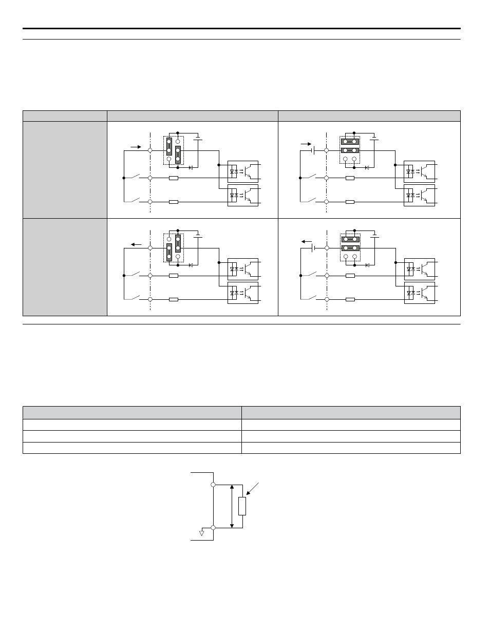
Sinking/Sourcing Mode Selection for Safe Disable Inputs
Note:
Terminals H1, H2, DM+, and DM- on 600 V class models are designed to the functionality, but are not certified to IEC/EN 61800-5-1,
ISO/EN 13849 Cat. 3, IEC/EN 61508 SIL2, Insulation coordination: class 1.
Use jumper S3 on the terminal board to select between Sink mode, Source mode or external power supply for the Safe Disable
(Default: Source mode, internal power supply).
Table 3.13 Safe Disable Input Sink/Source/External Power Supply Selection
Mode
Drive Internal Power Supply
External 24 Vdc Power Supply
Sinking Mode
24 Vdc
H1
H2
HC
Jumper S3
24 Vdc
H1
H2
HC
External
24 Vdc
Jumper S3
Sourcing Mode
24 Vdc
H1
H2
HC
Jumper S3
24 Vdc
H1
H2
HC
External
24 Vdc
Jumper S3
u
Using the Pulse Train Output
The pulse train output terminal MP can supply power or be used with an external power supply.
NOTICE: Connect peripheral devices in accordance with the specifications. Failure to comply may cause unexpected drive operation, and
can damage the drive or connected circuits.
n
Using Power from the Pulse Output Terminal (Source Mode)
The high voltage level of the pulse output terminal depends on the load impedance.
Load Impedance R
L
(kΩ)
Output Voltage V
MP
(V) (insulated)
1.5 kΩ
5 V
4 kΩ
8 V
10 kΩ
10 V
Note:
The load resistance needed in order to get a certain high level voltage V
MP
can be calculated by: R
L
= V
MP
• 2 / (12 – V
MP
)
MP
AC
V
MP
R
L
Load Impedance
Figure 3.32 Pulse Output Connection Using Internal Voltage Supply
3.8 Control I/O Connections
136
YASKAWA ELECTRIC TOEP C710616 41E YASKAWA AC Drive - A1000 Quick Start Guide