3 dr illing cy cles – HEIDENHAIN TNC 410 User Manual
Page 141
8 Programming: Cycles
128
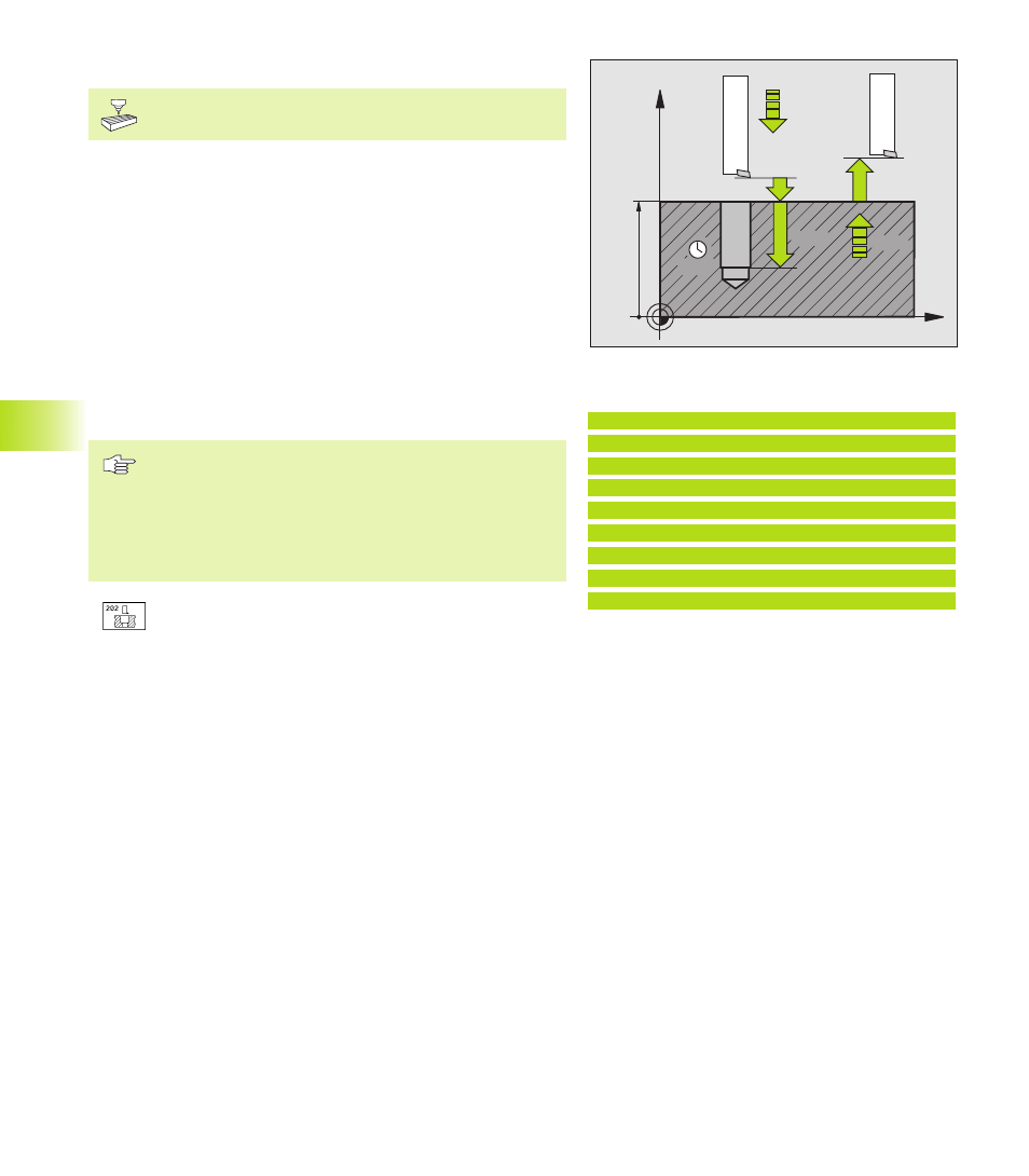
BORING (Cycle 202)
Machine and control must be specially prepared by the
machine tool builder to enable Cycle 202.
1 The TNC positions the tool in the tool axis at rapid traverse FMAX
to set-up clearance above the workpiece surface.
2 The tool drills to the programmed depth at the feed rate for
plunging.
3 If programmed, the tool remains at the hole bottom for the
entered dwell time with active spindle rotation for cutting free.
4 The TNC then orients the spindle with M19 to the 0° position
with an oriented spindle stop.
5 If retraction is selected, the tool retracts in the programmed
direction by 0.2 mm (fixed value).
6 The tool then retracts to set-up clearance at the retraction feed
rate, and from there — if programmed — to the 2nd set-up
clearance in FMAX.
Before programming, note the following:
Program a positioning block for the starting point (hole
center) in the working plane with RADIUS
COMPENSATION R0.
The algebraic sign for the cycle parameter TOTAL HOLE
DEPTH determines the working direction.
ú
Set-up clearance Q200 (incremental value): Distance
between tool tip and workpiece surface.
ú
Depth Q201 (incremental value): Distance between
workpiece surface and bottom of hole
ú
Feed rate for plunging Q206: Traversing speed of the
tool during boring in mm/min
ú
Dwell time at depth Q211: Time in seconds that the
tool remains at the hole bottom
ú
Retraction feed rate Q208: Traversing speed of the
tool in mm/min when retracting from the hole. If you
enter Q208 = 0, the tool retracts at feed rate for
plunging.
ú
Workpiece surface coordinate Q203 (absolute value):
Coordinate of the workpiece surface
ú
2nd set-up clearance Q204 (incremental value):
Coordinate in the tool axis at which no collision
between tool and workpiece (clamping devices) can
occur.
ú
Disengaging direction (0/1/2/3/4) Q214: Determine the
direction in which the TNC retracts the tool at the hole
bottom (after spindle orientation).
X
Z
Q200
Q201
Q206
Q211
Q203
Q204
Q208
8.3 Dr
illing Cy
cles
Example NC blocks:
9 CYCL DEF 202 BORING
Q200=2
;SET-UP CLEARANCE
Q201=-20
;DEPTH
Q206=150
;FEED RATE FOR PLUNGING
Q211=0.5
;DWELL TIME AT BOTTOM
Q208=500
;RETRACTION FEED TIME
Q203=+0
;SURFACE COORDINATE
Q204=50
;2. SET-UP CLEARANCE
Q214=1
;DISENGAGING DIRECTN