Vav/zone configuration, Vav/zone setpoint screens, Vcc-x operator interface sd 73 – Orion System VCC-X Controller User Manual
Page 73
VAV/ZONE CONFIGURATION
VCC-X Operator Interface SD
73
VAV/Zone Setpoint Screens
Setpoint Screen #3 - AHU Heat Call Space Temp
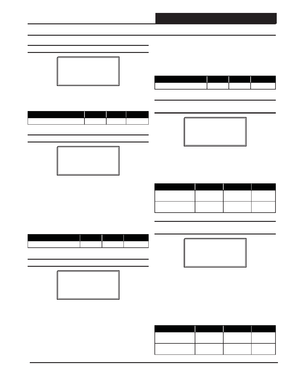
XX Box Spts IDXXXX
AHU Heat Call
Space Temp...: XXºF
This setpoint allows you to set a Space Temperature that will cause
the VAV/Zone Controller to send a call for heat to the HVAC unit.
This only occurs in the Unoccupied Mode.
Description
Minimum
Default
Maximum
AHU Heat Call Space Temp
50ºF
70ºF
90ºF
Setpoint Screen #4 - Auxiliary Heat Setpoint
XX Box Spts IDXXXX
Auxiliary Heat
Setpoint..: XXºF
This setpoint allows you to set a Space Temperature that will enable
the Auxiliary Heat Relay (Relay 4) on the VAV/Zone Controller
Reheat Expansion Board for heating options other than box heat,
such as baseboard heat or an external duct heater. This could control
a stage of electric heat or an on/off hot water valve. The Auxiliary
Heat Relay will energize at .5˚F below this setpoint and will de-
energize at .5˚F above this setpoint. The Auxiliary Heat will continue
to function regardless of the HVAC Mode the unit is in and at any
airfl ow condition.
Description
Minimum
Default
Maximum
Auxiliary Heat Setpoint
50ºF
70ºF
90ºF
Setpoint Screen #5 - Damper Airfl ow Integral
XX Box Spts IDXXXX
Damper/Airflow Spt
Integral [Ki]..: XXX
The VAV/Zone Controller normally opens its damper based on a
Proportional Error from Setpoint. That means if the zone temperature
is 4°F from setpoint, the damper would be 100% open, or it would be
modulating to provide the Maximum CFM on Pressure Independent
boxes. If the error is less than 4°F, the damper may stagnate at that
position and never satisfy the zone. If you add Integral into the
damper calculation process, this will cause the damper or airfl ow
calculations to continue to increase as long as the zone temperature
is still above the setpoint. That means it can provide 100% or Maxi-
mum CFM before the 4°F error is achieved, bringing the zone under
control faster than it normally would. Start with a small (5 or 10)
value, if you use this, and monitor the effect it has. If you enter too
large a value, you can create “hunting” situations that can cause the
damper actuator to prematurely wear out.
Description
Minimum
Default
Maximum
Integral
0
0
100
Setpoint Screen #6 - Damper Airfl ow Max &
Vent Min
XX Box Spts IDXXXX
Damper/Airflow Spt
Maximum..: XXX %
Vent Min.: XXX %
The VAV/Zone Controller will not allow the damper or airfl ow cal-
culation to exceed the Maximum setpoint while it is allowing the
damper to modulate. During Vent mode when there is no heating
or cooling demand, the damper or airfl ow will maintain at least the
Vent Min amount of airfl ow into the zone for ventilation.
Description
Minimum
Default
Maximum
Maximum
0% or 0 CFM
100% or
1000 CFM
100% or
30000 CFM
Vent Min
0% or 0 CFM
25% or
250 CFM
100% or
30000 CFM
Setpoint Screen #7 - Damper Airfl ow Cool/
Heat Minimum
XX Box Spts IDXXXX
Damper/Airflow Spt
Cool Min.: XXX %
Heat Min.: XXX %
During Supply Air Cooling Mode, if the space being served by this
damper is satisfi ed and has no cooling demand, the damper will
close to this Cool Min setting. This provides a minimum amount
of airfl ow into the space for ventilation, even if the space does not
require additional cooling. During Supply Air Heating Mode, if the
space being served by this damper is satisfi ed and has no heating
demand, the damper will close to this Heat Min setting. This provides
a minimum amount of airfl ow into the space for ventilation, even if
the space does not require additional heating.
Description
Minimum
Default
Maximum
Cool Min
0% or
0 CFM
10% or
1000 CFM
100% or
30000 CFM
Heat Min
0% or
0 CFM
10% or
100 CFM
100% or
30000 CFM
- VCB-X Controller VCB-X VCB-X Modular Service Tool VCM Controller Operator Interfaces SD VCM-X/RNE Controller VCC-X Modular System Manager SD Modular System Manager SD Quick Start VCM-X/RNE Controller Operator Interface SD SA E-BUS Controller VAV II Controller v.1 CAV II Controller v.1 MUA II Controller v.1 VAV II Controller v.2 CAV II Controller v.2 MUA II Controller v.2