Vcc-x setpoints, Vcc-x setpoint screens, Vcc-x operator interface sd 48 – Orion System VCC-X Controller User Manual
Page 48
VCC-X SETPOINTS
VCC-X Operator Interface SD
48
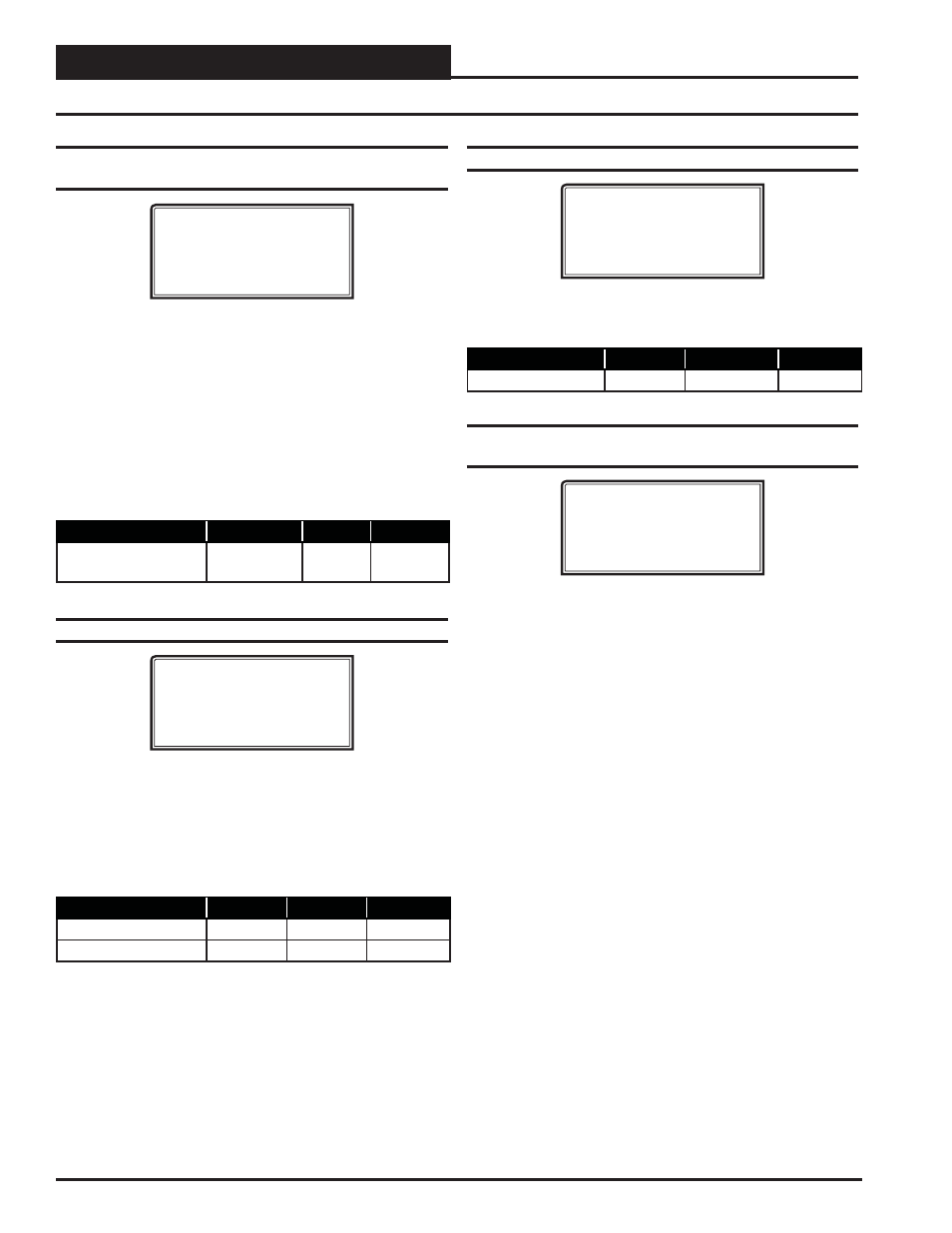
Setpoint Screen #27 - Economizer Maximum
Position in High CO
2
Level
VCC-X Spts ID:#
Econo Max Pos In
High CO2.: 50%
This Setpoint allows you to set the Maximum Position the Econo-
mizer will open if high CO
2
conditions occur in the space. The
Maximum Economizer Position Setpoint is used to limit the amount
of Outdoor Air that will be introduced to the HVAC unit in order to
ensure the unit is operating within its Heating and Cooling design
limitations. As shown in the table that follows, the Minimum setting
for this Setpoint is the value previously set for the Economizer Min
Position Setpoint.
CO
2
override cannot be used in conjunction with airfl ow control of
the Outdoor Air damper (previous screen) in this version.
Description
Minimum
Default
Maximum
Maximum Economizer
Position In High CO
2
Economizer
Min Position
50%
100%
Setpoint Screen #28 - CO
2
Setpoints Min/Max
VCC-X Spts ID:#
CO2 Setpoints
Min CO2: 900ppm
Max CO2: 1000ppm
The Min CO
2
Setpoint is the threshold CO
2
level at which the Econo-
mizer Min Damper Position (Setpoint Screen #24) will begin to be
reset higher. The Max CO
2
Setpoint is the CO
2
level at which the
Economizer Min Damper Position will be reset to the Econo Max
Pos In High CO
2
(Setpoint Screen #27). In between those CO
2
lev-
els, the Economizer Minimum Position will be proportionally reset
between the values set in Setpoint Screens #24 and #27.
Description
Minimum
Default
Maximum
Minimum CO
2
Level
0 PPM
900 PPM
2000 PPM
Maximum CO
2
Level
0 PPM
1000 PPM
2000 PPM
Setpoint Screen #29 - CO
2
Altitude Setpoint
VCC-X Spts ID:#
Altitude
Setpoint: 1000ft
Enter the distance above sea level for the installed CO
2
Sensor. Altitude
correction is required for valid readings if you are above 500 feet. High
limit = 15,000 feet; Low limit = 0 feet.
Description
Minimum
Default
Maximum
Altitude Setpoint
0 Feet
1000 Ft.
15,000 Ft.
Setpoint Screen #30 - Building Pressure
Setpoint & Deadband
VCC-X Spts ID:#
Building Pressure
Setpoint: 0.02”
Deadband: 0.01”
The VCC-X can maintain Building Static Pressure anytime the
Supply Fan is operating. A Building Pressure Transducer must be
connected to the VCC-X. The following are the available control
options.
Direct Acting Building Pressure Control
•
On/Off Exhaust Fan
—If an On/Off Exhaust Fan is
being used, a relay output must be confi gured for
“Exhaust Fan”. This relay will energize whenever the
Building Pressure rises above the Building Pressure
Setpoint by the Deadband amount. The relay will de-
energize when the Building Pressure falls below the
Building Pressure Setpoint by the Deadband amount.
•
Exhaust Fan VFD or Modulating Exhaust
Damper
—If confi gured for Modulating Exhaust, a user-
adjustable voltage output (AOUT4 – Building Pressure
Output on the VCC-X) will be used to control this fan or
damper. An Exhaust Relay can be confi gured if
necessary to enable the fan or damper. Whenever the
Building Pressure rises above the Building Pressure
Setpoint by the Deadband amount, the Exhaust Fan
Relay will energize and the Modulating Signal will
activate to control to the Building Pressure Setpoint. If
the Building Pressure falls below the Building Pressure
Setpoint by the Deadband amount, the Modulating
Signal will modulate towards 0% as it attempts to
maintain the Building Pressure Setpoint. The Exhaust
Fan Relay remains energized as long as the Modulating
Signal is above 0%.
VCC-X Setpoint Screens
- VCB-X Controller VCB-X VCB-X Modular Service Tool VCM Controller Operator Interfaces SD VCM-X/RNE Controller VCC-X Modular System Manager SD Modular System Manager SD Quick Start VCM-X/RNE Controller Operator Interface SD SA E-BUS Controller VAV II Controller v.1 CAV II Controller v.1 MUA II Controller v.1 VAV II Controller v.2 CAV II Controller v.2 MUA II Controller v.2