Vcc-x setpoints, Vcc-x setpoint screens, Vcc-x operator interface sd – Orion System VCC-X Controller User Manual
Page 43
VCC-X Operator Interface SD
VCC-X SETPOINTS
43
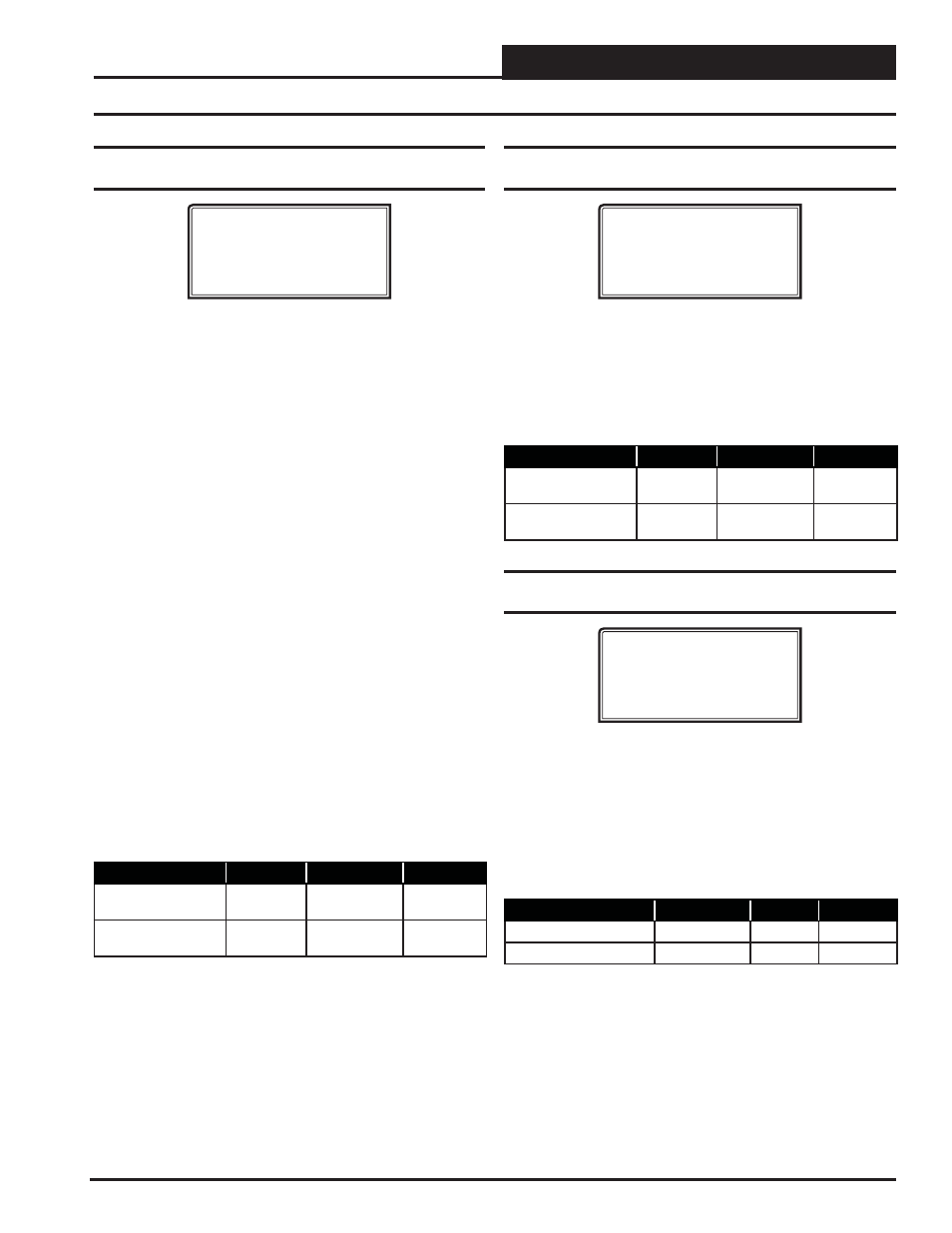
Setpoint Screen #10 - Indoor RH Setpoint Low
and High Reset Source
VCC-X Spts ID:#
Indoor RH Setpoint
Lo Rst Src: 50%
Hi Rst Src: 60%
This screen can be used to set the Space Humidity Setpoint and to
set the Space Humidity Reset range used to reset the Suction Coil
Temperature Setpoint.
On units where Indoor Humidity is used to initiate Dehumidifi cation
(non MUA units), the Low Reset Source (Lo Rst Src) is the Dehu-
midifi cation Setpoint, and as the Indoor Humidity rises above this
setpoint, Dehumidifi cation will be initiated. If the humidity falls 1%
below this setpoint, the unit will leave the Dehumidifi cation Mode.
If no reset of the Coil Temperature Setpoint is desired, set the High
Reset Source (Hi Rst Src) at the same value as the Low Reset Source.
If reset of the Coil Temperature Setpoint is desired, when the Indoor
Humidity rises above the Low Reset Source, Dehumidifi cation will
be initiated and the Coil Temperature Setpoint will be set at the
Coil Temperature High Reset Limit (confi gured in the next screen).
The High Reset Source (Hi Rst Src) is the Indoor Humidity level at
which the Coil Temperature will be reset to the Coil Temperature
Low Reset Limit (confi gured in the next screen). As the Indoor
Humidity rises between the Low Reset Source and the High Reset
Source, the Coil Temperature Setpoint will be proportionally reset
between the Coil Temperature High Reset Limit down to the Coil
Temperature Low Reset Limit.
On MUA units where the Outdoor Dewpoint Setpoint is used to
initiate Dehumidifi cation, this screen is only used to set the Indoor
Humidity values that will reset the Coil Temperature Setpoint. As de-
scribed above, as the Indoor Humidity rises within the range created
by the Low and High Reset Source Setpoints, the Coil Temperature
Setpoint will be proportionally reset between the High and Low Coil
Temperature Reset Limits.
Description
Minimum
Default
Maximum
Indoor RH Setpoint
Low Reset Source
0%
50%
100%
Indoor RH Setpoint
High Reset Source
0%
60%
100%
VCC-X Setpoint Screens
Setpoint Screen #11 - Coil (Saturation)
Temperature Low & High Reset Limits
VCC-X Spts ID:#
Coil Temp Setpoint
Hi Rst Lmt: 45ºF
Lo Rst Lmt: 40ºF
Based on the Indoor Humidity Reset Range confi gured on the pre-
vious screen, the Coil Suction (Saturation) Temperature Setpoint
can be reset between the High Reset Limit (Hi Rst Lmt) and Low
Reset Limit (Lo Rst Lmt) confi gured on this screen during the
Dehumidifi cation Mode. See the description of this reset function
on the previous screen. If the High Reset Limit and the Low Reset
Limit are set at the same value, no Coil Temperature Reset will occur.
Description
Minimum
Default
Maximum
Coil Temp Setpoint
High Reset Limit
35ºF
(1.7
º
C)
45ºF
(7.2
º
C)
70ºF
(21.1
º
C)
Coil Temp Setpoint
Lo Reset Limit
35ºF
(1.7
º
C)
40ºF
(4.5
º
C)
70ºF
(21.1
º
C)
Setpoint Screen #12 - Static Pressure
Setpoint & Deadband
VCC-X Spts ID:#
Static Pressure
Setpoint: 1.50”
Deadband: 0.10”
For VAV units, a Supply Fan VFD or Bypass Damper Actuator is
used to maintain the Duct Static Pressure Setpoint. The Static Pres-
sure Output Signal varies to control to the Static Pressure Setpoint.
The Duct Static Pressure is maintained at this setpoint anytime the
Main Fan is running.
The Duct Static Setpoint accuracy is controlled by this value. No
Main Fan VFD changes are made if the static is within this range
of this setpoint.
Description
Minimum
Default
Maximum
Static Pressure Spt
0.10″ WG
1.50″ WG
3.0″ WG
Deadband
0.01″ WG
0.10″ WG
0.50″ WG
- VCB-X Controller VCB-X VCB-X Modular Service Tool VCM Controller Operator Interfaces SD VCM-X/RNE Controller VCC-X Modular System Manager SD Modular System Manager SD Quick Start VCM-X/RNE Controller Operator Interface SD SA E-BUS Controller VAV II Controller v.1 CAV II Controller v.1 MUA II Controller v.1 VAV II Controller v.2 CAV II Controller v.2 MUA II Controller v.2