System connection, Modular system manager sd, Vcc-x operator interface sd 6 – Orion System VCC-X Controller User Manual
Page 6: Zone, Figure 3: modular system manager sd dimensions
Zone
Zone
SYSTEM CONNECTION
VCC-X Operator Interface SD
6
Modular System Manager SD
Modular System Manager SD
ENTER
CLEAR
ESC
PREV
NEXT
DOWN
UP
6
5
4
DEC
7
0
8
1
3
2
9
MINUS
-
STATUS
SETPOINTS
SCHEDULES
ALARMS
OVERRIDES
9.00"
6.25"
1.81"
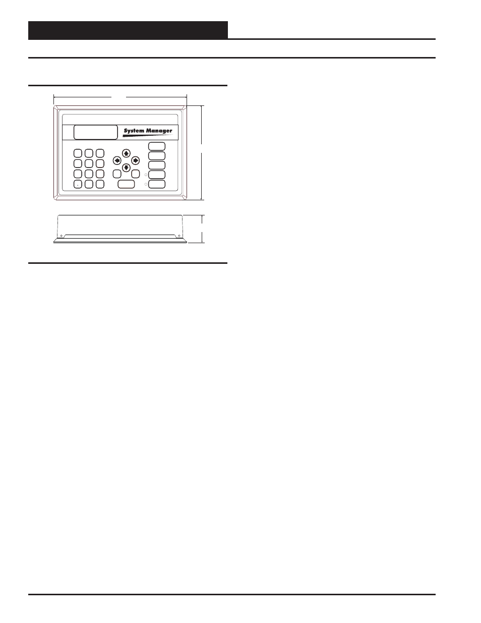
Figure 3: Modular System Manager SD Dimensions
The OE392-12 Modular System Manager SD provides a direct
link to enable you to view the status and adjust the setpoints of the
VCC-X, VCB-X, VCM-X, VCM-X E-BUS, RNE, SA E-BUS, VCM,
VAV/CAV, MUA II or VAV/Zone Controller on the control system
communications loop. The System Manager SD is housed in a beige-
colored plastic enclosure. The System Manager has a programmable
4 Gigabyte SD card and is equipped with a 4-line-by-20-character
backlighted display panel and a 24-key membrane keypad for data
selection and entry. All keypad operations are simple and straight
forward, utilizing non-cryptic plain English language messages.
Menu-driven programming allows for easy setup and operation
without the need for specialized training. The System Manager also
has 2 integral LEDs for user notifi cation of system alarm condi-
tions and override initiations. Protection from unauthorized users
is provided by the System Manager’s integral multi-level passcode
authorization programming.
On a Networked System, the Modular System Manager is connected
to the communications and power loop of the system via modular
cables that simply plug into the System Manager board and the
Power/Comm Distribution Board. This virtually eliminates wiring
errors and makes installation fast and easy. When it is to be con-
nected to a Stand-Alone system, a cable with modular connectors
on one end and stripped wire ends on the other end is provided to
facilitate connecting communications and power to the Modular
System Manager from the 24 VAC power source and the HVAC
unit controller communication wiring terminals.
The Modular System Manager is designed for wall mounting. Mount-
ing holes are provided to attach the Modular System Manager to a
standard handy box. It is recommended that the System Manager be
mounted at approximately eye level to allow for ease of program-
ming and reading of the display. The System Manager is typically
mounted in the building manager’s or superintendent’s offi ce or in
an equipment room. The attractive enclosure is quite suitable for
mounting in any location.
- VCB-X Controller VCB-X VCB-X Modular Service Tool VCM Controller Operator Interfaces SD VCM-X/RNE Controller VCC-X Modular System Manager SD Modular System Manager SD Quick Start VCM-X/RNE Controller Operator Interface SD SA E-BUS Controller VAV II Controller v.1 CAV II Controller v.1 MUA II Controller v.1 VAV II Controller v.2 CAV II Controller v.2 MUA II Controller v.2