Modular system manager sd, Setting the operating mode, Vcc-x operator interface sd 18 – Orion System VCC-X Controller User Manual
Page 18
Zone
Zone
MODULAR SYSTEM MANAGER SD
VCC-X Operator Interface SD
18
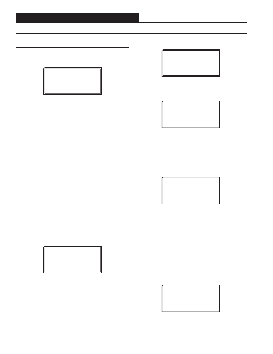
Setting the Operating Mode
Setting the Operating Mode
The Operating Mode is displayed on the last line of the Main Screen
as shown below. The factory default setting for the System Manager
is LS (Low Speed) Stand Alone Mode.
System Manager SD
Wednesday Operations
01/16/15 02:21 PM
LS Stand Alone Mode
The System Manager must be confi gured for the correct mode of
operation for your system. There are 5 modes of operation available
for the Orion System—LS (Low Speed) Stand-Alone, HS (High
Speed) Stand-Alone, LS (Low Speed) Network, HS (High Speed)
Network, and LS (Low Speed) & HS (High Speed) Multiple
MGRS.
If you are using this System Manager on a communications loop
that doesn’t have a MiniLink PD or CommLink connected to it and
you have a single System Manager on your system, then you need
to operate in LS (Low Speed) Stand-Alone Mode. If you are us-
ing a VCC-X Controller or GPC-XP Controller that is set for high
speed, and you don’t have a MiniLink PD or CommLink connected
to the loop, then you will need to change the setting to HS (High
Speed) Stand Alone Mode.
If you are using the System Manager on a communications loop
and have an installed MiniLink PD or CommLink, you will need to
change the setting to LS (Low Speed) Network Mode. If you are
using a VCC-X Controller or GPC-XP Controller that is set for high
speed, and are using a MiniLink PD or CommLink, then you will
need to change the setting to HS (High Speed) Network Mode.
If you are using this System Manager on a communications loop,
have a MiniLink PD or CommLink installed, and have multiple Sys-
tem Managers, then you need to operate in Multiple MGRS Mode.
If your display indicates a different mode than the one you need,
press
<2>
at the Setup Screen shown below. You will have to cycle
power to get to this screen or by pressing
and
.
1) Set Time & Date
2) Communications
NEXT) More Options
ESC) Exit Menu
T
he Passcode Clearance Screen will appear as shown below.
THIS ACTION REQUIRES
A SPECIAL HIGH LEVEL
PASSCODE CLEARANCE
Enter: XXXXXXX
Enter
the seven digit passcode
<2337377>
to access the next screen.
You will then see the screen below displayed.
Stand Alone Mode
Lo Speed Connection
Use Left/Right Arrow
To Change Selections
Press
<
>
or
<
>
if you need to change the mode of opera-
tion to LS (Low Speed) Stand-Alone, HS (High Speed Stand-
Alone, LS (Low Speed) Network, HS (High Speed Network,
LS (Low Speed) Multiple Manager or HS (High Speed)
Multiple Manager and then press
to save your
selection. If you are not using Multiple Manager Mode, press
at the screen below and continue scrolling right and left.
Multiple Manager
Unit Address: 0
Press ESC to Exit
For Multiple MGRS Mode, enter the address at which you want
this particular System Manager to be set.
When multiple System Managers are used on a local loop, each
must be set with a unique address different from any other device
on that loop. You must perform this same operation again for each
System Manager installed. If you want one of these System Manag-
ers to be able to indicate alarms and overrides for the entire system,
you must select either LS or HS Network Mode on that particular
System Manager.
Once you have the correct number per the display above displayed,
press
. The following screen will appear telling you that
you have changed the system mode:
You Have Changed The
System Manager Mode
Press Any Key To
Continue
Press
any key on the keyboard to exit this screen.
- VCB-X Controller VCB-X VCB-X Modular Service Tool VCM Controller Operator Interfaces SD VCM-X/RNE Controller VCC-X Modular System Manager SD Modular System Manager SD Quick Start VCM-X/RNE Controller Operator Interface SD SA E-BUS Controller VAV II Controller v.1 CAV II Controller v.1 MUA II Controller v.1 VAV II Controller v.2 CAV II Controller v.2 MUA II Controller v.2