CIRCUTOR CVM-B Series User Manual
Page 82
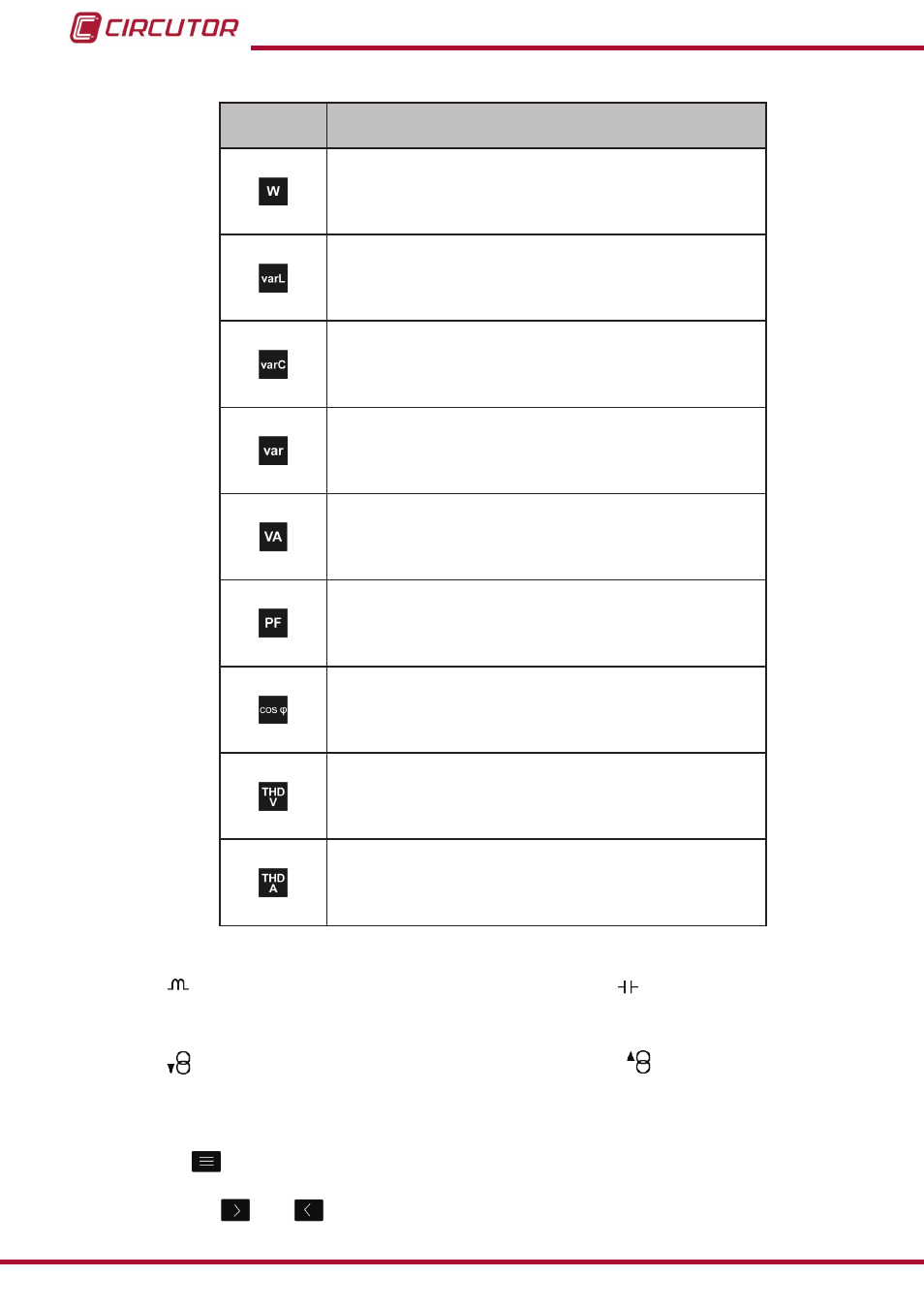
Table 17 ( Continuation) :Instantaneous parameters (display 4 parameters)�
Icon
Display 4 parameters
Instantaneous parameters
Active power L1
(2)
Active power L2
(2)
Active power L3
(2)
Active power III
(2)
Inductive reactive power L1
(2)
Inductive reactive power L2
(2)
Inductive reactive power L3
(2)
Inductive reactive power III
(2)
Capacitive reactive power L1
(2)
Capacitive reactive power L2
(2)
Capacitive reactive power L3
(2)
Capacitive reactive power III
(2)
Total reactive power L1
(1) (2)
Total reactive power L2
(1) (2)
Total reactive power L3
(1) (2)
Total reactive power III
(1) (2)
Apparent power L1
(2)
Apparent power L2
(2)
Apparent power L3
(2)
Apparent power III
(2)
Power Factor L1
(1) (2)
Power Factor L2
(1) (2)
Power Factor L3
(1) (2)
Power Factor III
(1) (2)
Cosine phi L1
(1) (2)
Cosine phi L2
(1) (2)
Cosine phi L3
(1) (2)
Cosine phi III
(1) (2)
Voltage THD L1
(2)
Voltage THD L2
(2)
Voltage THD L3
(2)
Voltage THD LN
(2)
Current THD L1
(2)
Current THD L2
(2)
Current THD L3
(2)
Current THD LN
(2)
(1)
The following icons appear for all these parameters on the screen:
Indicating that the parameter refers to inductive or
capacitive energy.
(2)
The following icons appear for all these parameters on the screen:
Indicating that the parameter refers to consumed or
generated energy.
If the 2 icons light up at the same time, it means the installation is not properly
connected.
Press the
key to display the lower area.
Use the keys
and
to browse the various parameters.
82
CVM-B100 - CVM-B150
Instruction Manual